Smart Pet Feeder Engineering Guide: Precision Dispensing, Anti-Jamming & Freshness Preservation for OEM/ODM Programs
Executive Summary: Condition → Solution → Red Flag Matrix
| Product Condition | Recommended Architecture | Accuracy Benchmark | Audit Verification Requirement |
|---|---|---|---|
| Precision-critical / prescription-diet SKU | Conveyor-belt + BLDC motor + Hall-sensor closed-loop | ±1–5 g per portion | Raw DVT logs with Cpk histograms across 20+ kibble types at ≥60% RH |
| Cost-optimized connected SKU | Auger + brushed DC motor | ±10–20% | Kibble-specific calibration records; jam-rate data by kibble type |
| Entry-level, non-precision SKU | Gravity-based gate mechanism | ±20–30% | Basic cycle-count data sufficient; no accuracy claim justified |
| Humid-market deployment (e.g., Florida, U.S. Gulf Coast, U.K., coastal Western Europe) | Three-layer freshness architecture: multi-layer silicone hopper seal + top-cover desiccant module + semi-closed dispensing zone | Near-zero food degradation at 75% RH / 21 days | Programmable environmental chamber test reports at 70–80% RH for minimum 21 days |
| Any connected SKU | OTA update infrastructure + battery-backed RTC (8–24 hr runtime) | N/A | OTA server ownership documentation; RTC retention test log across simulated interruption cycles |
Supplier Red Flags — Disqualifying Criteria:
- No OTA firmware update server infrastructure (unverifiable post-shipment patch capability)
- Inability to produce raw, statistically validated DVT logs across multiple kibble profiles
- No in-house programmable humidity chamber or EMI-shielded test facility
- "Anti-jam" claims lacking current-sensing firmware logic and event-log documentation
- Defect rate stated as a one-time claim rather than tracked as a rolling batch-level metric
- Food-contact safety referenced without traceable third-party test report numbers
Manufacturer Capability Snapshot: TAILNTAIL (Dongguan Youpu Pet Electronic Technology Co., Ltd.)
For procurement teams evaluating OEM/ODM partners, the following documented infrastructure serves as a reference benchmark for qualified smart pet feeder manufacturing:
- Facility: 10,000 m² manufacturing facility, Dongguan, Guangdong, China (established 2018)
- Production capacity: 120,000–150,000 units per month across flexible configurations
- SMT capability: 8 semi-automatic SMT lines with AI vision AOI generating timestamped defect records per board
- Quality metrics: Rolling batch-level OQC defect rate below 0.3‰, tracked across IQC/IPQC/OQC nodes
- In-house reliability lab: EMI-shielded anechoic chamber, programmable temperature/humidity chambers, salt-spray tester, wire-bending test rig
- Certifications: ISO9001:2015, TÜV Rheinland, CE, FCC, RoHS, FDA food-contact (third-party verified)
- Patented engineering platforms: Conveyor-belt feeder design patent (ZL202330452246.7), current-sensing anti-jam alarm implemented alongside patented feeder alarm system (Utility Model ZL202321876540.9), dual-app smart control module design patent (ZL202330452230.7)
This guide applies the same documentation standards described throughout to any supplier under evaluation — including the one referenced here.
Introduction & Market Dynamics
A smart pet feeder is, in functional terms, a precision dosing appliance deployed in an uncontrolled domestic environment. Unlike industrial dispensing equipment operating under continuous supervision, a feeder must perform reliably across years of autonomous cycles — handling variable kibble geometry, fluctuating ambient humidity, occasional power interruptions, and end users who are not present to observe individual feeding events.
The global smart pet feeder market has grown alongside broader pet humanization trends and premium pet nutrition adoption. This growth has created a procurement challenge: segment expansion has attracted suppliers offering specification-identical products differentiated only by housing color and app UI. For OEM/ODM brand owners, selecting a manufacturing partner on the basis of published specifications without engineering verification is a post-launch liability. Portion accuracy claims, anti-jam capability statements, and freshness architecture descriptions are only as reliable as the test documentation behind them.
This guide examines the three engineering pillars that separate a brand-defining feeder from a commodity one — precision dispensing, anti-jam reliability, and freshness preservation — at the mechanical and systems level. It integrates the smart pet feeder OEM development timeline, compliance requirements, and factory audit methodology. The goal is to equip procurement professionals and product managers with enough technical vocabulary to interpret supplier claims accurately and recognize genuine engineering depth during factory evaluation. Where specific documented capabilities are cited, they reference the publicly verifiable infrastructure of TAILNTAIL (Dongguan Youpu Pet Electronic Technology Co., Ltd.) as an industry-available benchmark.
Chapter 1: Precision Dispensing Mechanisms — Conveyor-Belt vs. Auger Accuracy Comparison
The dispensing mechanism is the single most consequential engineering decision in a smart feeder. It directly determines portion accuracy, kibble compatibility, anti-jam susceptibility, and long-term field reliability.
1.1 Gravity-Based Dispensing
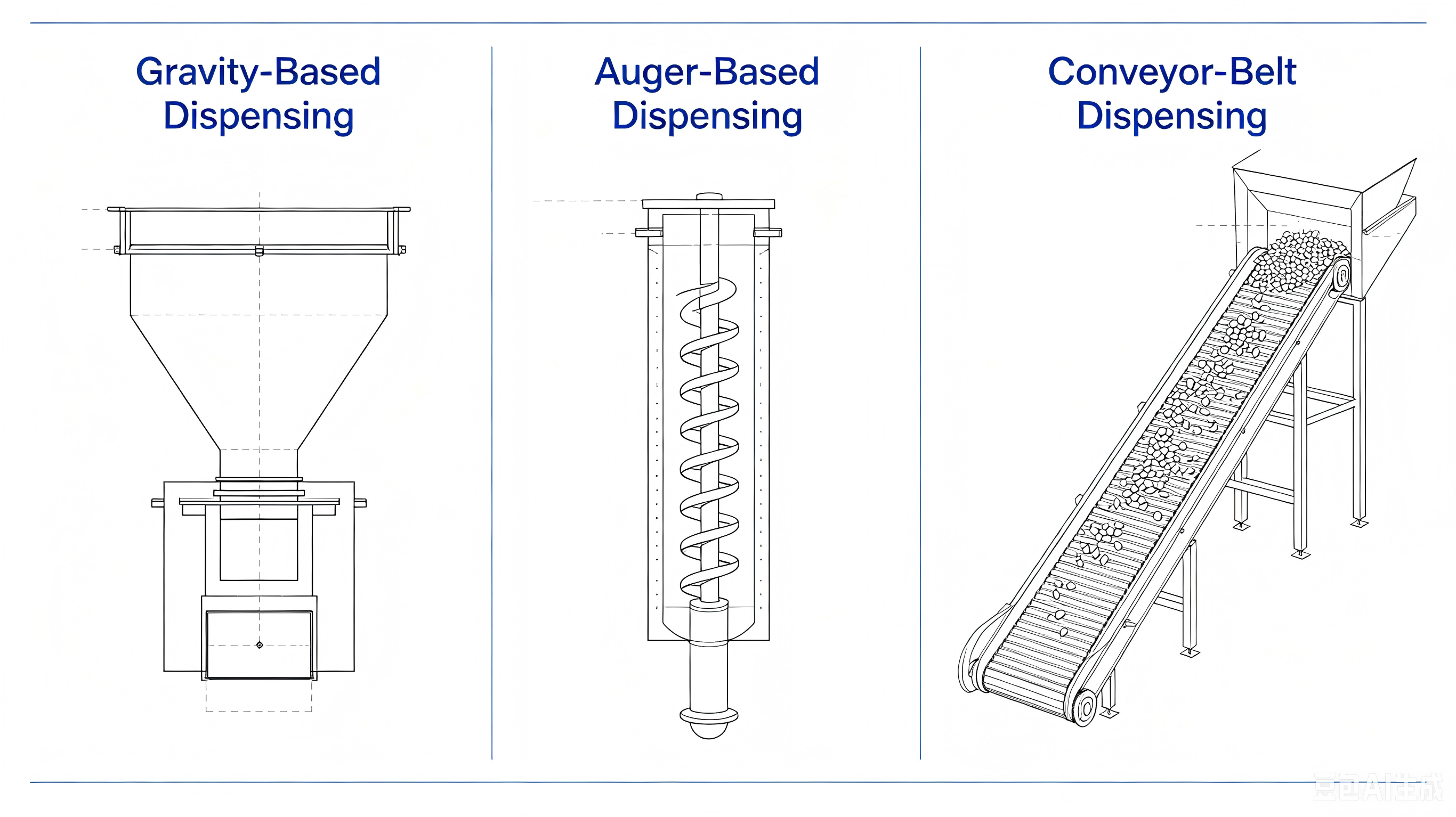
Architecture: A rotating disc or fixed gate at the hopper base meters food by allowing gravity to drive material through an aperture. Component count is minimal; mechanical failure points are limited.
Accuracy Benchmark: ±20–30% of target portion weight under controlled conditions. In humid environments or mixed-kibble configurations, variance is higher and less predictable due to kibble bridging (arch formation across the aperture), irregular geometry, and moisture-induced clumping.
Validation Requirement: Basic cycle-count data is sufficient for entry-level programs. No portion-accuracy specification is defensible on a gravity platform, and buyers should reject any accuracy claim made against this architecture.
Buyer Action: Request cycle-count and failure-mode documentation. Confirm the supplier makes no accuracy claims in product specifications.
Business Impact: Gravity systems are architecturally unsuitable for any connected feeder where portion accuracy is a user expectation or brand specification. Launching a connected SKU on this mechanism exposes the brand to accuracy-related review and return-rate risk from the first product cycle.
1.2 Auger-Based Dispensing
Architecture: A helical screw inside a cylindrical channel loads food from the hopper, carries it forward by rotation, and discharges it at the output end. Portion size is controlled by motor rotation count or timed operation.
Accuracy Benchmark: ±10–20%. Variance is driven by irregular kibble fill of the auger channel: round, cylindrical, and star-shaped kibble occupy the same channel volume with different mass, and this dimensional variance translates directly into portion weight variance per rotation. Kibble-specific calibration profiles narrow the range but degrade as auger geometry changes with wear or when users switch formulations.
Validation Requirement: Kibble-specific calibration records per target food type; jam-rate data per kibble type; documented failure-mode analysis for bridging at hopper throat and kibble fracture in the channel.
Buyer Action: Request calibration records across all kibble types in the target product specification. Ask for jam-rate data per kibble type at both dry and humid test conditions.
Business Impact: Auger systems are appropriate for mid-tier connected feeders where ±10–15% accuracy meets user expectations, provided robust anti-jam measures and kibble-specific calibration are implemented. Treating an auger-based platform as precision-tier without the supporting calibration infrastructure will generate accuracy complaints in markets where prescription or portion-controlled feeding is the use case.
1.3 Conveyor-Belt Dispensing
Architecture: A belt or chain-driven carrier moves food along a linear path from the hopper to the discharge point. A Hall-effect sensor or optical encoder monitors belt position in real time, providing continuous feedback to a motor controller that adjusts output to achieve a calibrated belt displacement corresponding to the target portion weight. Drive: brushless DC motor for lower electromagnetic interference, longer rated service life (no brush wear), and quieter operation during scheduled overnight cycles.
Accuracy Benchmark: ±1–5 g per portion under validated conditions. The fundamental accuracy advantage over auger architecture: portion volume is determined by directly measured belt travel distance, not by inference about food fill in a rotating cavity. This feedback loop substantially decouples portion accuracy from kibble shape variation.
Validation Requirement: Raw DVT logs with Cpk variance histograms across a minimum of 20 kibble profiles at ambient humidity levels representative of target markets (≥60% RH for humid-market programs). Logs must include portion weight data per run, ambient conditions (temperature and RH), and statistical analysis — not only a summary report. Premium conveyor-belt platforms with Hall-sensor feedback and BLDC motor control, documented in systems holding design patents such as TAILNTAIL's ZL202330452246.7, have consistently achieved this accuracy tier across validated kibble profiles.
Buyer Action: Request raw DVT logs — not formatted summary reports. Confirm the Cpk analysis covers 20+ kibble types and includes at-humidity testing. If a supplier cannot produce this documentation, treat their accuracy claim as unverified.
Business Impact: This is the only architecture appropriate for any OEM program where portion accuracy is a core product claim, a brand positioning element, or a specification for prescription-diet or multi-pet feeding use cases. Mechanism selection must precede tooling cost evaluation.
1.4 OEM/ODM Program Decision Matrix
| Priority Class | Recommended Mechanism | Mass Production Lead Time | Standard Certifications | Minimum Audit Requirement | Tooling NRE |
|---|---|---|---|---|---|
| Precision / clinical / multi-pet | Conveyor-belt + BLDC + Hall sensor | 20 days post-design freeze | CE (RED/LVD/EMC), FCC, RoHS 2.0, FDA food-contact | Raw DVT logs with Cpk histograms across 20+ kibble types | Contact for project quotation |
| Mid-tier connected | Auger + brushed DC | 20 days post-design freeze | CE, FCC, RoHS 2.0 | Kibble-specific calibration records; jam-rate documentation | Contact for project quotation |
| Entry-level / non-connected | Gravity gate | 20 days post-design freeze | CE, RoHS 2.0 | Basic cycle count; no accuracy claim justified | Contact for project quotation |
| Custom housing / logo branding (any tier) | Any | 20 days post-design freeze | As above per tier | Outgoing defect rate tracking records | Scope-dependent |
Housing-only color and logo customization is available at standard industry MOQ thresholds without additional mechanism tooling cost. Contact manufacturer for scope-based quotation.
Note: Reach and WEEE certifications are available upon request as assisted application.
1.5 Mechanism Comparison Summary
| Parameter | Gravity | Auger | Conveyor-Belt |
|---|---|---|---|
| Typical Accuracy | ±20–30% | ±10–20% | ±1–5 g closed-loop |
| Motor Type | Low-torque brushed DC | Brushed DC | Brushless DC |
| Key Failure Mode | Bridging, moisture clumping | Kibble variance, calibration drift | Belt slip, sensor fouling |
| Kibble Compatibility | Limited | Moderate | High |
| Relative BOM Cost | Low | Medium | Medium-High |
| Recommended Tier | Entry-level | Mid-tier connected | Premium / clinical |
Chapter 2: Anti-Jamming Engineering — Mechanical & Electronic Integration
Anti-jam reliability is a layered system, not a single feature. A dispenser jam during a scheduled feeding event is one of the most consequential field failure modes in the feeder segment: the owner discovers a missed meal after the fact, not in real time. For reliability-positioned products, this failure generates disproportionately negative reviews and elevated return rates. Designing against jams requires addressing both the probability of jam occurrence (mechanical architecture) and the consequences when a jam occurs anyway (electronic detection and firmware recovery).
2.1 Mechanical Anti-Jam: Preventing Blockages by Design
Dispensing path geometry is the primary variable. Narrow channel sections, abrupt direction changes, and sharp internal corners create natural pinch points where irregular kibble shapes can lodge. Channel sizing must accommodate the largest kibble in the target product range, with generous transition radii throughout the path.
For track-based systems, low-dust track geometry limits kibble fragmentation. Fine-particle accumulation from fractured kibble acts both as an abrasive accelerating mechanical wear and as a binding agent contributing to bridging and elevated motor load — a dual degradation mechanism.
Hopper throat exit angle is a secondary variable. Angles too shallow promote bridging; too steep creates freefall that overloads the mechanism. The appropriate geometry is validated empirically across a representative kibble range during DVT, because kibble shape distribution, surface coating, and moisture content are not consistently characterized by food manufacturers and cannot be derived analytically.
Mechanical design reduces jam frequency and severity. It cannot eliminate jams entirely, because food properties vary across brands, batches, and storage conditions. Electronic detection covers the residual case.
2.2 Electronic Anti-Jam: Current-Sensing Firmware and Automated Recovery
The electrical basis of current-sensing anti-jam is direct: a motor driving increasing mechanical resistance consumes proportionally more current. Monitoring motor current in real time detects a developing jam before complete stall — which occurs only after the obstruction has fully engaged.
Implementation requires a current-sensing element in the motor drive circuit (typically a low-value shunt resistor with an amplifier stage) and firmware that compares real-time current against a learned baseline for the operating cycle. Elevated current above a configurable threshold triggers the recovery sequence before a full blockage forms.
Automated Recovery Sequence:
- Detect motor current exceeding jam threshold above learned baseline
- Reverse motor direction — applies a different force vector to the obstruction rather than compressing it
- Retry forward motion
- If cleared: resume normal operation and write event to persistent log
- If not cleared after defined retry count: halt operation → push app notification → write event to persistent log
Reversing before retrying is more effective than increasing forward torque because the reverse vector tends to dislodge rather than compress the obstruction. The retry limit prevents mechanical damage from repeated attempts against a hard blockage. The app alert provides actionable information to the user; the event log provides field reliability data for firmware and design iteration. Platforms with this architecture — implemented alongside our patented feeder alarm system (Utility Model ZL202321876540.9) — have demonstrated self-recovery capability that reduces missed-meal events without user intervention for minor obstructions.
2.3 DVT Validation: Multi-Kibble Testing at Real-World Conditions
An anti-jam system validated only on the manufacturer's reference kibble is not meaningfully validated. Kibble geometry, density, and surface coating vary substantially across brands and formulations. Soft-moist kibble behaves differently from hard biscuit formulas. Small-breed kibble (5–8 mm diameter) presents different bridging dynamics than large-breed kibble (15–20 mm diameter).
OEM Pet Feeder Anti-Jam DVT Requirements:
- Minimum 20 kibble types covering round, cylindrical, star-shaped, and irregular geometries
- Extended cycle counts (thousands of dispensing events per kibble type) for statistically meaningful jam-rate data
- Testing at elevated ambient humidity (60–80% RH) for products targeting high-humidity regions such as the Southeastern U.S., Florida, the U.K., and coastal Northern Europe
- Documented jam-event rate per kibble type at each test condition
2.4 Green Flags vs. Red Flags: Anti-Jam Audit Checklist
| Evaluation Criterion | Green Flag | Red Flag | Document to Request |
|---|---|---|---|
| Anti-jam detection method | Current-sensing firmware with configurable threshold | "Mechanical anti-jam design" only — no electronic detection | Motor drive circuit schematic confirming current-sense element |
| Recovery logic | Reverse-retry-alert-log sequence with defined retry limit | Forward torque increase only, or no recovery logic described | Firmware specification document for jam-recovery routine |
| Kibble validation breadth | DVT records across 20+ kibble types | Testing on 1–3 reference kibbles only | Raw DVT jam-rate logs per kibble type |
| Humidity validation | Jam-rate data at 60–80% RH | Dry-lab conditions only | Test condition metadata in DVT records |
| Event logging | Persistent log accessible to engineering team | No event log; no field data collection | Sample event log from field or DVT unit |
| Claims basis | Raw test records available on request | "Anti-jam technology" in spec sheet only | DVT summary plus supporting raw data on request |
2.5 Common Supplier Claims & How to Verify Them
| Supplier Claim | What It Might Mean | Verification Question |
|---|---|---|
| "We have anti-jam technology" | May be mechanical geometry only — no electronic detection, no firmware, no event logging | Is the anti-jam implementation current-sensing firmware with reverse-retry logic, or only mechanical path geometry? Can you provide the motor drive circuit schematic and firmware specification? |
| "Our feeder never jams" | Tested on one reference kibble under dry conditions | What was the kibble test matrix? How many cycle counts per type? At what ambient humidity? |
| "Anti-jam validated in DVT" | DVT may have used only 1–3 kibble types | How many distinct kibble geometries were in the DVT matrix? Are the raw jam-event-rate logs available by kibble type? |
| "Automatic jam recovery" | May be only power-cycle-and-retry, not current-sensing | What triggers recovery — user power cycle, timed retry, or real-time current threshold? What is the retry logic and limit? |
| "Firmware handles jams" | May be incomplete without persistent logging and app notification | Does the firmware write a persistent event log? Does it push an app notification on unresolved jam? |
Chapter 3: Freshness Preservation Architecture
Food freshness failure is a design problem, not a user behavior problem. Dry pet food is hygroscopic — it absorbs ambient moisture and undergoes staling through oxidative rancidity of fat content. In a feeder hopper holding several liters of food over days or weeks, even modest humidity ingress accelerates both processes measurably.
Field Case Study (Anonymized, 2023): A field analysis of returned feeders from a distributor in the U.S. Gulf Coast (Florida) found that 68% of food degradation complaints traced to single-layer hopper seals combined with un-isolated dispensing zones. Upgrading to a three-layer silicone architecture — validated under 75% RH for 21 days in a programmable environmental chamber — reduced field failures to near-zero. Similar patterns have been observed in coastal U.K. and Western European markets during humid summer months. The failure mode was systematic and design-attributable; end-user behavior was not the variable. This case illustrates why pet feeder humidity chamber testing must be validated with documented chamber data, not extrapolated from dry-condition specifications. Manufacturers such as TAILNTAIL maintain in-house programmable humidity chambers as part of their reliability lab infrastructure, enabling this validation without external lab dependencies.
3.1 Three-Layer Freshness Architecture
The Three-Layer Freshness Architecture addresses humidity ingress at three distinct points in the food storage and delivery path.
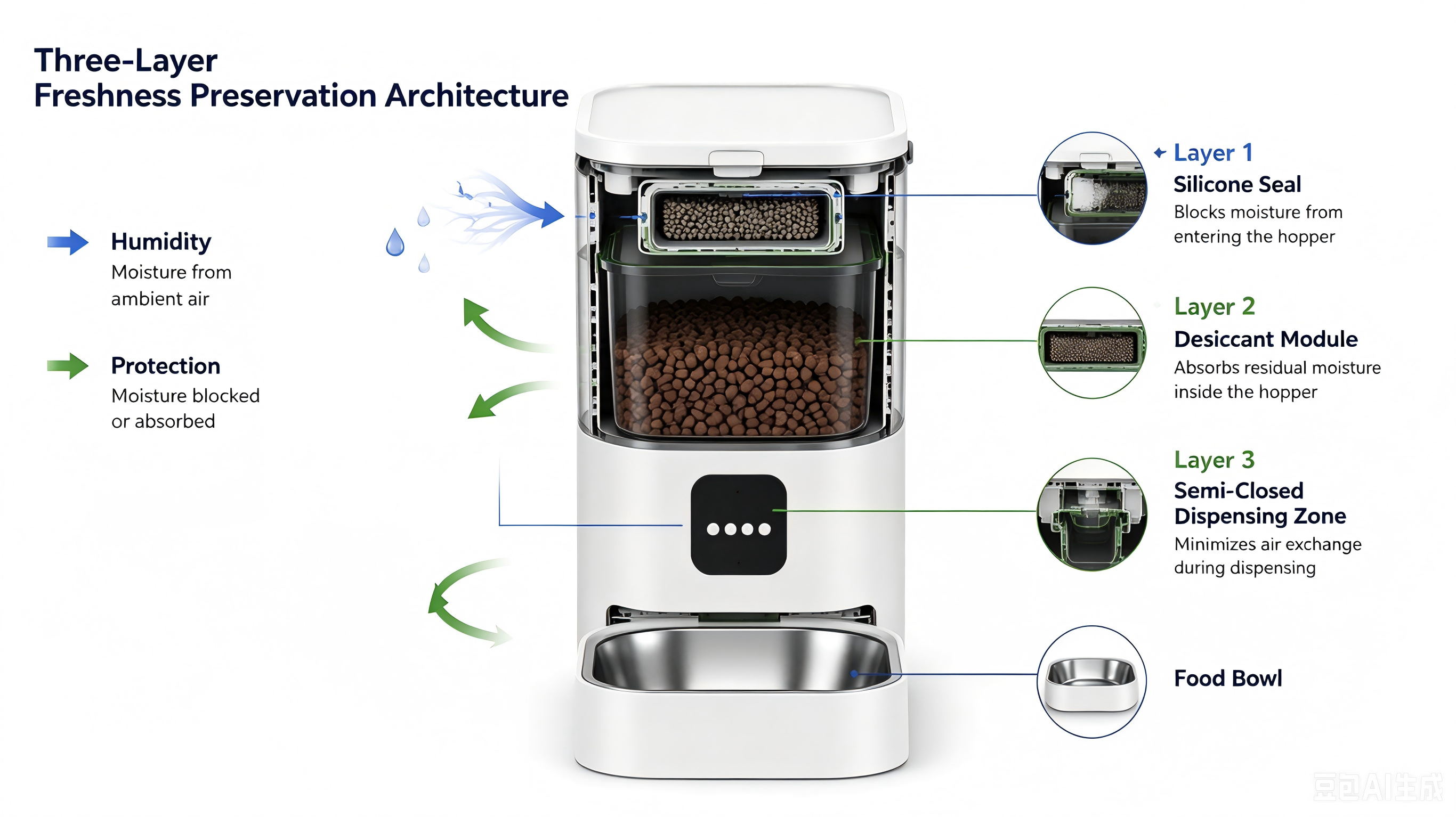
Layer 1 — Hopper-Level Sealing
A multi-layer silicone seal at the hopper lid provides compliant surface contact that accommodates minor dimensional variation from manufacturing tolerances and thermal cycling. Silicone is the appropriate material: it retains elasticity across a wide temperature range, resists compression set better than TPE alternatives, and has established food-contact-safe grades in CE, FDA, and PSE regulatory frameworks. This is the primary barrier against ambient humidity ingress.
Business Impact: A single-layer or non-silicone hopper seal tested only under dry conditions will produce humidity-related food degradation complaints in high-humidity regions such as the U.S. Gulf Coast, Florida, the U.K., and coastal Western Europe — regions that represent significant and growing pet tech demand.
Layer 2 — Active Desiccant Management
No passive seal is perfectly impermeable, and food itself introduces moisture at load time. A desiccant module positioned close to the food mass provides active absorption to compensate for minor ingress. User-replaceability is a critical design requirement: a desiccant that cannot be conveniently replaced will not be replaced, progressively degrading function. Integration into the top cover — directly above the hopper — meets both proximity and accessibility criteria.
Business Impact: A desiccant module that is difficult to access or replace will be ignored by users within the first few months of ownership, converting an engineered freshness feature into a marketing claim with diminishing real-world performance over the product's service life.
Layer 3 — Dispensing Zone Isolation
Food advanced into or near the dispensing mechanism is exposed to a larger air exchange volume than food sealed in the hopper. A semi-closed dispensing zone limits air circulation to only the food actively being metered, reducing oxidative exposure of the queued portion.
Business Impact: Products validated across all three layers in documented programmable environmental chamber protocols at 75% RH / 21 days have demonstrated near-zero degradation rates in field conditions matching the high-humidity profiles of the U.S. Southeast, Florida, and Western European coastal regions. This differentiation is directly verifiable by requesting chamber test reports — and verifiable differentiation commands premium positioning.
3.2 Material Selection: 304 Stainless Steel vs. ABS for Food-Contact Surfaces
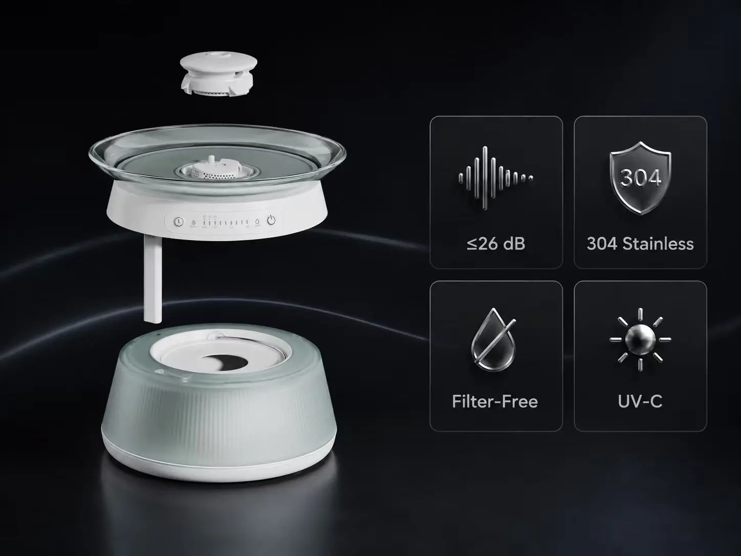
304 stainless steel food-contact compliance directly impacts long-term hygiene performance and regulatory positioning:
| Property | 304 Stainless Steel | ABS Plastic |
|---|---|---|
| Biofilm adhesion | Low (non-porous, smooth surface) | Higher (micro-porosity enables colonization with use) |
| Plasticizer migration | None | Possible with fat-containing kibble at elevated temperature |
| Cleanability | Food-safe with standard household agents | Scratch sites accumulate over use cycles |
| Corrosion resistance | High (food acids, salt) | Moderate |
| Regulatory compliance | FDA food contact: straightforward with grade verification | Formulation-dependent; specific grade verification required |
| Manufacturing complexity | Higher tooling complexity | Lower |
| RF / Wi-Fi challenge | Partial Faraday cage effect; requires antenna window engineering | RF-transparent; no antenna architecture constraint |
The antenna engineering challenge of all-metal housings is solvable but requires intentional planning at PCB layout and mechanical design stages. A deliberate antenna window — a non-conductive panel or gap in the metal structure — positioned for adequate RF propagation without structural compromise is the standard resolution. This must be designed into the RF architecture from the outset; it cannot be addressed by material specification alone.
FDA food-contact compliance for 304 stainless steel should be verified by traceable third-party test reports from a recognized laboratory, specifying the tested components, test method, and results for regulated substances including lead and cadmium. Suppliers who provide only an "FDA compliant" statement without a report number are not providing verifiable compliance documentation; request the actual report.
Chapter 4: Power, Connectivity & Firmware Lifecycle Management
4.1 Mains Power with Battery-Backed RTC
A smart feeder operates on a scheduled feeding cycle. If a power interruption resets the device's clock state or causes missed scheduled events, the user's configured feeding times are disrupted — an immediately visible reliability failure.
The correct power architecture combines mains power as the primary source with an integrated lithium battery backup and a charge/discharge management circuit. The management circuit monitors mains input status and switches to battery output within milliseconds of an interruption, without triggering a reboot cycle that would reset RTC state. RTC retention through power interruption and restoration is a non-negotiable functional requirement: scheduled feeding times must be preserved, and the first post-restoration feeding event must occur at the correct time.
Battery capacity should be sized for 8–24-hour runtime, spanning a typical residential power interruption. Regional grid reliability data for target markets should inform sizing decisions — markets with frequent short interruptions have different requirements than those with rare extended outages. Battery safety documentation should be backed by recognized certification (KC certification and TÜV Rheinland CB test reports are established references for this product class).
4.2 OTA Infrastructure: Non-Negotiable for Connected SKUs
OTA firmware update capability is a baseline requirement for any connected feeder. The Wi-Fi connection providing scheduling and monitoring also provides a delivery channel for firmware updates — enabling post-shipment correction of field-discovered issues without service calls or product returns.
Products without OTA infrastructure cannot be patched after shipment. Every firmware-level deficiency identified post-launch becomes a permanent field liability. For OEM buyers managing multi-SKU portfolios, OTA enables feature deployment across installed base — a meaningful commercial capability as product lines evolve. Qualified OEM manufacturers, such as TAILNTAIL, maintain documented OTA server infrastructure with defined service-level agreements and rollback capability, as part of their connected product engineering baseline.
OTA Supplier Audit Questions:
- Who controls the OTA update server infrastructure — the manufacturer, a third-party SaaS provider, or the OEM brand?
- What is the update delivery mechanism and device-side authentication protocol?
- What is the rollback capability if an update creates new issues in the field?
- How are deployment rates and device response monitored across the device population after a release?
- What is the contractual commitment for OTA server maintenance over the product's expected service life?
- If the manufacturer ceases operations, who assumes server infrastructure responsibility?
Dual-App Ecosystem Deployment: For OEM programs requiring retailer-channel compatibility alongside proprietary brand apps, the relevant architecture is a smart control module supporting concurrent dual-app protocol stacks — enabling Tuya-ecosystem integration for retail channel requirements while maintaining a proprietary app experience for direct-to-consumer programs. Smart control module design patents such as TAILNTAIL's ZL202330452230.7 document this architecture. Buyers should confirm which protocol stacks the module supports, whether both can be active concurrently or require firmware variant selection, and who controls server infrastructure for each stack.
4.3 PCB Reliability for Long-Life Appliance Operation
A smart feeder executing continuous scheduled cycles in a kitchen environment operates as an embedded appliance for three to five years in warm, humid conditions with periodic power cycling. PCB design must reflect this operating profile:
- Component derating: Capacitors, transistors, and regulators selected for higher voltage or current than the nominal operating point extend component life under continuous operation. Electrolytic capacitors rated for 105°C ambient provide substantially longer service than 85°C-rated equivalents in kitchen conditions — a material reliability difference, not a marginal one.
- Conformal coating: PCB conformal coating provides protection against humidity-induced corrosion on board surfaces, a real failure mechanism in environments where cooking steam intermittently introduces moisture. This adds a manufacturing processing step but materially improves field reliability in humid operating conditions — a relevant design decision for any feeder targeting Southeast Asian or high-humidity regional markets.
Chapter 5: B2B Quality Validation Framework
5.1 OEM Pet Feeder Development Timeline: EVT → DVT → PVT → Mass Production
A stage-gated development process provides structured decision points that prevent quality problems from propagating into production.
EVT (Engineering Verification Test): Initial functional samples from design freeze. Goal: verify core engineering architecture works as specified. EVT samples typically use temporary tooling and are not cosmetically representative. Standard lead time: 15 days from design freeze for a manufacturer with design capability and tooling infrastructure in place.
DVT (Design Verification Test): Samples from near-final tooling and processes, validated against the full performance specification. DVT is where anti-jam performance is validated across kibble types, portion accuracy is confirmed at scale, freshness architecture is tested under humidity conditions, and regulatory pre-compliance screening is conducted. Standard DVT duration: 60–90 days. DVT is the stage most commonly compressed under schedule pressure — and DVT compression is the most common cause of post-launch quality issues in OEM/ODM programs. Buyers must verify DVT was fully executed, not shortened to meet a launch date.
PVT (Production Verification Test): Validates that the manufacturing process itself, at production-representative volumes, produces units meeting the DVT-validated specification. PVT surfaces process-sensitive defects not visible in small DVT batches.
Mass Production: Standard lead time: 20 days after DVT sign-off for a manufacturer with stable tooling and supply chain. Programs claiming significantly shorter timelines are either reusing previously validated platforms with cosmetic changes, or have compressed DVT.
Total EVT-to-first-mass-production: 90–120 days for a complete new program. Custom housing color or logo branding programs with no mechanism modification can be completed faster, at standard industry MOQ.
5.2 The OEM Pet Feeder Supplier Audit Checklist: 12 Non-Negotiables
| # | Audit Item | Green Flag | Red Flag | Document to Request |
|---|---|---|---|---|
| 1 | Portion accuracy validation methodology | Cpk histograms across 20+ kibble types at ≥60% RH with raw weight data | Single-kibble or summary-only test report | Raw DVT portion-weight logs, not formatted summary |
| 2 | Anti-jam implementation | Current-sensing firmware with reverse-retry-alert-log logic (implemented alongside patented feeder alarm system, e.g., Utility Model ZL202321876540.9 architecture) | Mechanical geometry claim only; no firmware specification | Motor drive schematic + jam-recovery firmware spec |
| 3 | OTA server infrastructure | Manufacturer-controlled server with defined SLA; rollback capability | Third-party SaaS with no contractual continuity; no OTA at all | OTA architecture documentation; server ownership confirmation |
| 4 | Defect rate tracking | Rolling batch-level OQC defect rate below 0.3‰, documented across prior 6–12 months | Single stated figure, no batch traceability | Batch-level OQC records from last 6–12 months |
| 5 | Humidity chamber validation | Programmable environmental chamber test reports at 70–80% RH / 21 days | "Tested under humidity" without chamber data or conditions | Chamber test reports with equipment calibration records |
| 6 | Food-contact safety documentation | Third-party test reports with traceable reference numbers | "FDA compliant" without supporting test report number | Test report numbers; request traceable documents |
| 7 | Multi-node quality framework | IQC / IPQC / OQC documented as separate checkpoints with aggregate tracking | Single end-of-line visual inspection only | Quality manual; IQC and IPQC procedure records |
| 8 | In-house lab capability | EMI anechoic chamber, programmable temp/humidity chambers, salt-spray tester, wire-bend rig | Reliance on third-party labs only for all testing | On-site lab equipment list with calibration certificates |
| 9 | AOI integration on SMT lines | AI vision AOI generating timestamped defect records per board | No AOI; manual visual inspection only | Sample AOI defect log from a recent production run |
| 10 | Certifications — current validity | CE, FCC, RoHS, PSE, FDA, ISO9001, TÜV — current certificates with issue and expiry dates | Expired certificates; certificates for different SKU variants | Certificate copies with issuance dates; confirm applicability to the program SKU |
| 11 | Production traceability | Batch-level traceability linking finished unit to production context | No batch traceability; no WMS or equivalent system | WMS traceability demonstration for a recent production batch |
| 12 | R&D iteration depth | Component-level prototyping with documented iteration cycles; DVT revision logs | First-pass samples presented as DVT without iteration records | DVT revision log; engineering change order records |
5.3 RFQ Email Template: 8 Questions to Send Your Supplier
Subject: Technical Qualification Questions — [Your Brand] Smart Pet Feeder OEM Program
Dear [Supplier Contact],
We are evaluating manufacturing partners for an OEM smart pet feeder program targeting [market/tier]. Before advancing to commercial discussion, we require answers to the following technical questions:
- Portion accuracy validation: Can you provide raw DVT logs — not formatted summary reports — including Cpk variance histograms across a minimum of 20 kibble types, tested at ≥60% RH? Please confirm the number of kibble profiles and dispensing cycles in your most recent DVT.
- Anti-jam architecture: Is your anti-jam implementation current-sensing firmware with reverse-retry-alert-log logic, or mechanical geometry only? Please provide the firmware specification document and confirm whether Utility Model ZL202321876540.9 or equivalent architecture applies.
- OTA server infrastructure: Who controls the OTA firmware update server? What is the rollback capability? What is the contractual commitment for server maintenance over the expected product lifecycle?
- Defect rate documentation: Please provide batch-level OQC records from the past 6–12 months showing rolling defect rate at outgoing inspection. A single stated figure is not sufficient for qualification.
- Humidity chamber testing: For freshness architecture claims, can you provide programmable environmental chamber test reports documenting food-degradation performance at 70–80% RH for a minimum of 21 days? Please include equipment calibration records.
- Food-contact safety: Please provide third-party test report reference numbers confirming food-contact surface compliance. "FDA compliant" statements without traceable report numbers are not acceptable for qualification.
- In-house lab capability: Please confirm whether your facility includes: EMI-shielded anechoic chamber, programmable temperature/humidity chambers, salt-spray tester, and wire-bending test rig. Provide equipment list and calibration status.
- Certifications — current validity: Please provide copies of current CE, FCC, RoHS, PSE, FDA, ISO9001, and TÜV certificates with issue and expiry dates, confirmed applicable to the platform being quoted.
We are targeting a [precision / mid-tier / entry-level] SKU with [conveyor-belt / auger] mechanism, [market targets], and [MOQ] for the first production order. Please confirm your capacity availability and standard lead times.
[Your name and title]
5.4 Manufacturing Infrastructure Reference Benchmark
As a reference point for what qualified manufacturing infrastructure looks like at scale: a 10,000 m² facility operating 8 semi-automatic SMT lines with AI vision AOI and an integrated industrial WMS, maintaining a rolling batch-level defect rate below 0.3‰ across IQC/IPQC/OQC nodes, with an in-house reliability lab featuring an EMI-shielded anechoic chamber, programmable temperature and humidity chambers, salt-spray testers, and wire-bending test rigs, represents the infrastructure floor for credible OEM/ODM feeder production at scale. Capacity in this infrastructure tier supports 120,000–150,000 units per month across flexible production configurations. This benchmark is documented from TAILNTAIL's Dongguan facility, and procurement teams are encouraged to verify equivalent capabilities in any supplier under evaluation.
Chapter 6: Certification & Global Market Readiness
6.1 Compliance by Global Market
| Market | Required Certifications / Standards | Notes |
|---|---|---|
| EU | CE (RED — radio equipment; LVD — low voltage; EMC — electromagnetic compatibility); RoHS 2.0; REACH* | CE is mandatory for any connected device sold in the EU. REACH coordination requires documentation management; allow time in program schedule. (*Assisted application available) |
| United States | FCC (radio frequency); FDA food-contact compliance | FDA food-contact compliance must be verified by third-party test reports with traceable reference numbers. 304 stainless steel and food-grade plastics each require specific grade verification. |
| United Kingdom | UKCA (UK Conformity Assessment, post-Brexit; replaces CE for GB market) | UKCA must be obtained separately from CE; documentation and marking requirements differ. |
| High-Humidity Markets (e.g., Florida, U.S. Gulf Coast, U.K., Western Europe) | No additional mandatory certification beyond existing FCC (US)/CE (EU)/UKCA; high-humidity performance validation strongly recommended. | Ambient humidity in these regions often exceeds 70–80% RH seasonally. 21-day programmable chamber testing (70–80% RH) should be treated as a design validation gate to minimize food degradation field failures. |
| Factory Baseline | ISO9001:2015 (quality management system); TÜV Rheinland certification (product safety and quality) | Both should be held concurrently. Request certificate issuance dates and confirm current validity. |
| Battery Safety | KC certification (Korea); TÜV Rheinland CB test reports (international) | Required for any product with integrated rechargeable cells. |
| Additional Markets | ETL (North American alternative to UL); ERP (EU energy-related products); WEEE* | ETL is recognized by OSHA as a Nationally Recognized Testing Laboratory and accepted by most North American retailers. (*Assisted application available) |
6.2 Certification Lead-Time Guidance
Program Planning Note: Certification is a sequential process with fixed lab scheduling dependencies. Regulatory lab scheduling, documentation preparation, and test execution add meaningful time to the program schedule that cannot be compressed by starting later.
For international distribution programs, certification planning must begin at DVT — not at PVT. A manufacturer with in-house pre-compliance testing capability identifies and resolves compliance issues during DVT rather than at the certification lab — materially reducing schedule risk and avoiding the significant rework cost of a compliance failure discovered at the PVT or production stage.
| Certification Stream | When to Initiate | Parallel Activity |
|---|---|---|
| CE (RED/LVD/EMC) | At DVT entry | Parallel with DVT reliability testing |
| FCC | At DVT entry | Parallel with DVT reliability testing |
| FDA food-contact | At material selection / DVT | Can be initiated as soon as materials are locked |
| UKCA; High-humidity validation (U.S. Southeast/Europe) | At DVT entry | Parallel; allow for longer lab scheduling for UKCA; initiate humidity chamber testing early in DVT to align with target market climates |
| ISO9001 / TÜV | Ongoing factory certification; verify current validity | Not program-specific; request current certificate at supplier qualification |
Chapter 7: FAQ — Technical Procurement Engineering Questions
Q1: How is portion accuracy validated, and what methodology is acceptable for OEM DVT sign-off?
Portion accuracy validation requires gravimetric measurement — a calibrated scale recording actual dispensed weight per portion — across a statistically meaningful sample of dispensing cycles, using multiple kibble types covering the target product range. For conveyor-belt platforms, DVT validation must include Cpk analysis with variance histograms across a minimum of 20 kibble profiles at humidity levels representative of target markets (≥60% RH for programs targeting high-humidity regions such as Florida, the U.S. Gulf Coast, the U.K., or coastal Europe). The DVT records must include raw weight data per portion per run, ambient conditions (temperature and RH), kibble type identification, and the full statistical summary — not only the aggregate average. A single-kibble, dry-condition test is not acceptable for sign-off on an accuracy specification. If a supplier presents only aggregate accuracy claims without underlying multi-kibble data, treat the specification as unverified.
Q2: How does dual-app ecosystem deployment work in OEM programs, and what does it mean for retail channel strategy?
Dual-app ecosystem deployment enables a feeder platform to operate under two app frameworks simultaneously — for example, integrating with the Tuya open-platform ecosystem for retailers requiring Tuya-ecosystem compatibility, while maintaining a proprietary app experience for direct-to-consumer programs. The architectural requirement is a smart control module supporting both communication protocol stacks, routing scheduling, history, and alert functions through either app interface without functional degradation. Smart control module design patents such as ZL202330452230.7 cover this architecture. For OEM buyers, the commercial implication is significant: a platform supporting dual-stack deployment can be listed through Tuya-ecosystem retailers without requiring a separate SKU or PCB revision. Confirm which stacks are supported, whether both can be active concurrently or require a firmware variant selection, and who controls server infrastructure for each stack.
Q3: How should I interpret a supplier's stated defect rate, and what is the industry benchmark?
A stated defect rate is only meaningful if it is: (a) measured at a defined stage — IQC, IPQC, or OQC; (b) tracked as a rolling batch-level metric, not a one-time claim; and (c) supported by production records traceable to specific batches. The benchmark for a qualified OEM feeder manufacturer at the OQC stage is a rolling defect rate below 0.3‰ (three-tenths of one per thousand units). During a supplier audit, request batch-level OQC records from the preceding 6–12 months rather than a single stated figure. The trend and variance across batches is more informative than any single data point. Suppliers who cannot produce these records should not be qualified for precision-tier programs regardless of price position.
Q4: What does "anti-jam" actually mean when a supplier says it, and how do I verify the claim?
"Anti-jam" encompasses a wide range of implementations — from basic mechanical channel geometry to a full current-sensing, reverse-retry, event-logging firmware system. The difference in field reliability between these implementations is significant. A mechanical-only anti-jam design reduces jam frequency but cannot detect or recover from jams that do occur. Current-sensing firmware with reverse-retry logic detects a developing obstruction before complete stall, executes an automated recovery sequence, logs the event, and notifies the user if recovery fails. When a supplier claims anti-jam capability, ask: Is detection mechanical only, or does it include real-time motor current monitoring? Is there a reverse-retry firmware routine? Is there a persistent event log? Platforms documented with utility models such as ZL202321876540.9 cover feeder alarm architecture; buyers should verify current-sensing implementation separately. If a supplier cannot answer these questions technically, the claim is a specification statement, not an engineering fact.
Q5: Why is humidity chamber testing critical for high-humidity regions like Florida, the U.S. Gulf Coast, or Western Europe?
Ambient humidity in regions such as the U.S. Gulf Coast, Florida, the U.K., and coastal Western Europe can regularly exceed 70–80% RH during warmer months. These conditions accelerate hygroscopic moisture absorption and oxidative rancidity in dry pet food — the same degradation mechanism observed in tropical climates. Field data from distributor programs in high-humidity U.S. and European regions has confirmed that single-layer seal architectures produce systematic degradation complaints in these conditions; three-layer architectures validated at these parameters have demonstrated near-zero degradation rates. Treat any freshness claim not backed by humidity chamber test reports as untested for these markets.
Q6: How do I verify FDA food-contact compliance claims?
FDA food-contact compliance for feeder food-contact surfaces should be verified by third-party test reports with traceable reference numbers from a recognized laboratory. The relevant tests measure migration of regulated substances — including lead and cadmium — from the food-contact surface under standardized extraction conditions. Acceptable documentation format: a test report with a unique reference number, specifying the tested components, test method, and results for each regulated substance. Suppliers who provide only an "FDA compliant" statement without a report number are not providing verifiable compliance documentation; request the actual report. For stainless steel components, "lead and cadmium non-detectable" is the expected result for correctly specified 304 stainless steel; equivalent documentation should be obtained for any food-contact material used in the dispensing path.
Q7: What is a realistic OEM pet feeder development timeline, and where do programs most often lose schedule?
A complete OEM smart pet feeder program — new mechanism, tooling, and firmware from design freeze to first mass production — requires 90–120 days under a well-managed process: approximately 15 days EVT, 60–90 days DVT (including multi-kibble validation, freshness testing, and pre-compliance screening), and 20 days PVT through mass production ramp. Programs claiming significantly shorter timelines without using a previously validated platform are, in practice, compressing DVT — which transfers defects to the post-launch phase. Custom housing color and logo branding programs on validated platforms complete faster, at standard industry MOQ thresholds. Schedule risk is highest at DVT: kibble validation across 20+ types at humidity, OTA infrastructure validation, and regulatory pre-compliance each require calendar time that cannot be compressed without accepting quality trade-offs.
Q8: What production capacity and customization scope should I confirm before selecting an OEM partner?
For a qualification-stage capacity assessment, confirm: monthly unit capacity (a facility capable of 120,000–150,000 units/month across flexible production configurations supports both initial scale programs and growth to meaningful volume); SMT line count and automation level (8+ semi-automatic SMT lines with AOI is a reasonable infrastructure floor for precision electronics production); customization scope (housing color, LOGO, packaging, hopper capacity, mechanism type, app stack); and lead times (15-day prototype, 20-day mass production after DVT sign-off represents the benchmark for a manufacturer with tooling infrastructure in place). Confirm whether MOQ thresholds vary by customization scope — mechanism changes carry different tooling requirements than cosmetic changes, and these should be quoted separately.
Chapter 8: Conclusion & Strategic Next Steps
Dispensing precision, anti-jam reliability, and freshness preservation are not independent features — they are interdependent engineering systems. A high-accuracy conveyor-belt mechanism susceptible to jamming delivers unreliable portions. An anti-jam system validated on one kibble type provides false assurance of real-world performance. A freshness architecture that seals the hopper but allows air circulation through the dispensing zone is only partially effective.
For OEM/ODM brand owners, engineering evaluation is a supplier qualification competency, not an academic exercise. Products that enter the market with unresolved accuracy, anti-jam, or freshness design gaps will surface those deficiencies in customer reviews, return rates, and retailer feedback within the first product cycle — effects more expensive to reverse than the engineering investment required to prevent them.
The evaluation standard is consistent regardless of price tier or target market: documented engineering evidence — raw DVT records, Cpk variance histograms, reliability test data, humidity chamber validation reports, production traceability — takes precedence over specification claims. A supplier who can produce this documentation and explain the engineering basis for their design decisions is the appropriate partner for a long-term OEM production relationship.
Strategic Next Steps for OEM Procurement Teams:
- Define accuracy tier and mechanism requirement using the Decision Matrix in Chapter 1 before issuing RFQs. Mechanism selection must precede tooling cost evaluation.
- Send the RFQ Email Template (Chapter 5.3) to all candidate suppliers before advancing to commercial discussion. Use responses to filter qualified from unqualified partners at the documentation stage.
- Request raw DVT logs as a qualification gate for any precision-tier program. Suppliers unable to produce Cpk histograms across 20+ kibble types at humidity should not advance to commercial negotiation.
- Confirm OTA server infrastructure ownership during technical diligence — not at contract signing. Post-shipment firmware liability is a program risk.
- Build certification planning into the DVT stage, not PVT. For multi-market programs spanning the EU, U.S., and high-humidity regions (e.g., Florida, U.K.), integrate humidity chamber validation into the DVT schedule alongside parallel regulatory lab engagement.
- Validate humidity chamber testing with actual test report documents for programs targeting high-humidity regions such as the U.S. Southeast, the U.K., and coastal Western Europe.
The smart pet feeder OEM development timeline of 90–120 days from design freeze to first production is achievable with a qualified manufacturing partner. Compressing that timeline by skipping DVT stages is not a cost saving — it is a post-launch liability transfer.
Engineering Benchmark Note
The infrastructure benchmarks cited throughout this guide — 10,000 m² manufacturing facility, 8 semi-automatic SMT lines with AI vision AOI, in-house EMI-shielded anechoic chamber, programmable temperature and humidity chambers, salt-spray testers, wire-bending test rigs, ISO9001:2015 and TÜV Rheinland certification (2023), rolling OQC defect rate below 0.3‰, and production capacity of 120,000–150,000 units per month — are documented characteristics of Dongguan Youpu Pet Electronic Technology Co., Ltd. (brand name TAILNTAIL), established 2018, Dongguan, Guangdong, China. These specifics are cited as a documented example of what qualified manufacturing infrastructure looks like at this production scale, not as uniqueness claims.
Design patents including ZL202330452246.7 (conveyor-belt feeder platform design), Utility Model ZL202321876540.9 (feeder alarm system), and design patent ZL202330452230.7 (smart control module with dual-app ecosystem capability) are publicly registered and verifiable through China's State Intellectual Property Office.
Product certifications held by the P9 smart pet feeder platform include CE certificate and CE-EMC test report (HUT2012522-1EC), FCC test report (HUT2012523-2F), and RoHS certificate and RoHS test report (HUT2012625-1R) — representing the documentation standard buyers should request for any feeder program under evaluation.
Procurement teams are encouraged to apply the same documentation standards described in this guide to any supplier under evaluation — including the one referenced here.
This guide is intended for procurement managers and product managers at pet tech brands engaged in OEM/ODM program evaluation. Technical claims reflect documented engineering benchmarks and publicly available compliance data current as of the publication date. All NRE and unit cost figures are scope-dependent; contact potential manufacturing partners directly for project-specific quotations.