Smart Pet Feeder & Fountain App Integration: A Technical Guide for OEM Buyers
Published by TAILNTAIL | Dongguan Youpu Pet Electronic Technology Co., Ltd.
Who This Guide Is For
This guide is written for OEM brands, private label startups, and product managers evaluating smart pet feeder OEM manufacturers or smart pet fountain OEM suppliers. If you need to bring a connected pet device to market—and you want to avoid the integration failures that cause returns and damage brand reputation—this is for you.
We're not going to spend time on marketing claims. We'll walk through the real engineering challenges, the specific failure modes, and what "production-ready" actually requires from a manufacturing partner.
1. Three Integration Failures That Kill Connected Pet Devices
In our analysis of connectivity returns across partner brands, three root causes consistently account for the majority of field failures. None are random. All are preventable.
Failure 1: Protocol Stack Collapse in Real RF Environments
What happens: A device pairs perfectly on a single 2.4 GHz test router in the factory lab. It ships. It fails in end-user homes with dual-band mesh networks, hidden SSIDs, or high-density apartment building interference.
Root cause: The pairing firmware and antenna design were never stress-tested against production-representative RF conditions before tooling.
What production-ready validation looks like: Devices should be tested under multi-router interference scenarios—multiple active routers on overlapping 2.4 GHz channels, combined SSID environments, and with production PCB antenna placement—before design lock. This is why we operate an in-house EMI pre-compliance testing chamber as a production gate, not an optional service. Validation happens on production-representative electronics, not engineering development boards. When a device leaves our facility, its RF performance has already been proven against the kind of congested network environment your customers actually live in.
Failure 2: Power Transients Resetting the Connectivity Module
What happens: The device works when idle. It disconnects when the motor runs or the pump activates. These "phantom disconnects" are difficult to reproduce in basic QA but happen constantly in real use.
Root cause: Inductive load spikes from motors, pumps, and UVC modules create voltage transients on the power rail feeding the Wi-Fi or BLE module. Without independent power domains and validated decoupling networks, these transients trigger module resets mid-session.
What production-ready design looks like: The motor/pump subsystem and the connectivity module should have separate power domains. Decoupling network design—capacitor selection, ground plane isolation, power path routing—must be validated on the production PCB, not just the prototype. This is particularly critical for smart feeders with dispensing motors drawing inrush current during activation, and smart fountains combining pump, UVC, and wireless modules on a single board. A pet owner triggering a manual feed from the office should see the camera stream stay live and the app remain connected while the motor dispenses—that baseline experience is what power-domain separation delivers.
Failure 3: Function Lock-In at the App Layer
What happens: A factory delivers a device paired to a white-label app. The OEM brand later discovers they cannot independently push firmware OTA updates, change alert thresholds, modify reporting cadence, or connect the device to their own app ecosystem. The "integration" was done once and frozen.
Root cause: Firmware logic, cloud configuration, and app functions were developed as a monolithic block rather than a modular architecture.
What production-ready architecture looks like: The app function set, alert logic, and reporting cadence should be separated from the firmware core. This allows post-launch configuration changes without a full firmware release cycle. Brands that plan to eventually integrate with their own applications should verify that API documentation and cloud access are available, and that data ownership is contractually clear from the start.
Production-Ready App Integration Defined
A production-ready connected device is one whose hardware, firmware, and app functions have been jointly validated for mass production stability—not merely demonstrated in lab conditions. Our internal benchmark is a field defect rate below 0.3‰ on connected devices, confirmed across 30-unit burn-in testing per production batch and tracked against 2024–2025 full-production data under our ISO9001 and TUV-certified quality system.
Connectivity failures trace to specific, predictable integration gaps in RF validation, power isolation, and software architecture. When you're evaluating a manufacturing partner, ask to see their pre-tooling validation data for each of these three failure modes. If the data doesn't exist, the risk hasn't been addressed.
2. What "App-Ready" Hardware Actually Means
"App-ready" is a commercial term without a standard technical definition. Here are four verifiable checkpoints we use to define it internally.
Checkpoint 1: Validated RF Performance
Pairing firmware must be stress-tested under real RF interference conditions. This means running pairing cycles against multiple active routers on overlapping 2.4 GHz channels, using production-representative PCBs with final antenna placement. Devices that don't meet stability thresholds don't proceed to tooling.
Checkpoint 2: Modular Function Architecture
A production-efficient connected product isn't built from scratch for each OEM project. It's assembled from a pre-validated function library—a set of hardware reference designs, firmware interfaces, and known certification scopes. Our library includes:
- Remote scheduling and real-time dispensing logs
- Video monitoring and two-way voice communication
- Radar-based occupancy sensing (180° detection)
- UVC water sterilization control
- Water level telemetry and filter-life alerting
- Battery-backed power management with charge control
Each module has a defined integration cost, a known certification scope, and a documented firmware interface. Selecting pre-validated modules reduces integration engineering from months to weeks.
Checkpoint 3: Power Resilience Design
An app-connected device that goes offline during a power interruption loses user trust immediately. For smart feeders, this means integrated lithium battery support so core dispensing and scheduling functions continue during outages. This requires coordinated design of the battery management IC, charge controller, and power-path switching circuit—all validated with the connectivity module to prevent brown-out resets. For fountains, wireless battery operation eliminates corded power as a placement constraint entirely.
Checkpoint 4: Pre-Compliance RF Validation
Submitting a device to a certification lab after design freeze is high-risk. A radiated emissions failure at that stage typically requires a PCB respin—adding 6–10 weeks and significant NRE cost. Our process runs pre-compliance EMI scanning during hardware development, not after. Radiated emissions, conducted emissions, and ESD susceptibility are characterized before the design is locked. This doesn't replace certified lab submission, but it significantly reduces the probability of first-submission failure—protecting both your launch timeline and your budget from the most common certification setback.
"App-ready" only means something when anchored to specific, verifiable engineering checkpoints. When a supplier uses that term, ask whether they can produce a pre-compliance EMI scan report for your specific product configuration. If they can't, the certification timeline is still at risk.
3. The OEM Integration Workflow: From PRD to Production
Here's the structured path from a Product Requirements Document to a mass-production-ready, app-connected device.
Stage 1: Functional Scoping and Risk Assessment
Timeline: 1–2 weeks
What happens: Each requested app function is mapped to one of three status codes: (A) available as pre-validated module, (B) available with integration engineering required, or (C) not recommended due to certification timeline or hardware constraints. Every function tagged (B) or (C) comes with a specific risk statement and an alternative recommendation.
Output: A Function Feasibility Matrix that eliminates the most common project failure mode: discovering that a feature is technically complex six weeks before sample delivery.
Stage 2: Hardware-in-the-Loop Samples
Timeline: 15 days from BOM lock
What happens: A physical sample running all specified app functions is delivered for evaluation. The sample uses production-representative electronics—not a development board—so RF performance, power behavior, and sensor response reflect what will actually ship. A reference app (iOS + Android) is provided for functional evaluation.
Sample policy: Hardware-in-the-loop samples are provided for functional evaluation; sample costs are deductible from the first mass production order.
Stage 3: Branding and App Deployment
What happens: Brand assets (logo, color system, icon set, app name) are applied to the validated function base. The OEM controls app identity and function configuration—which features are enabled, alert thresholds, reporting intervals. OEMs retain full ownership of end-user data; we act as a data processor. For brands that wish to integrate their own applications, API documentation is available.
Stage 4: End-of-Line Validation and Mass Production
What happens: 100% end-of-line connectivity verification. Every unit is assigned a unique device ID, provisioned to the cloud backend, put through an automated pairing test sequence, and passed only upon successful app handshake. Units that fail the pairing gate are pulled for engineering review—they do not ship.
Mass production lead time after sample approval: 20 days.
Project timeline summary:
| Project Type | PRD to First Shipment |
|---|---|
| Platform-based (existing enclosure) | 8–12 weeks |
| Custom hardware (new enclosure/mold) | 16–24 weeks |
A structured four-stage workflow—scoping, hardware validation, branding, and production provisioning—moves integration risk from "we'll fix it in the field" to "we verified it before the molds were cut." When evaluating suppliers, look for a defined stage-gate process, not an open-ended development timeline.
4. Technical Architecture: Four Layers of a Connected Pet Device
Understanding the layers helps OEM buyers evaluate supplier capabilities and identify potential failure points.
Layer 1: Device Hardware
Microcontroller, motor or pump (PWM or stepper control), environmental sensors (water level, radar or infrared occupancy, temperature), actuators (UVC LED, solenoid), and where applicable, integrated lithium battery with charge management.
For precision feeding applications, we use a track-based stepper motor with optical encoder feedback, validated across 10,000 dispensing cycles using standard kibble (diameter 8–12mm), maintaining ±1g dispensing accuracy. For fountain applications, pump selection and UVC module integration must account for both electrical noise characteristics and service life requirements.
Layer 2: Connectivity
Wi-Fi and BLE module, antenna design, and RF management firmware. This is the highest-risk layer for field failures. Antenna positioning must account for metallic enclosure elements and motor EMI sources. For devices with stainless steel housings—which significantly attenuate 2.4 GHz signals—the antenna must be routed to a PCB area with a cleared ground plane and proximity to a non-metallic aperture. This is confirmed in pre-compliance scans before PCB release.
BLE is typically used for initial device onboarding (pairing) due to its lower-power, short-range reliability. Wi-Fi handles operational telemetry and command delivery. Wi-Fi/BLE coexistence is managed at the firmware scheduler level.
Layer 3: Cloud Platform
Device identity management (unique device ID per unit), command queue delivery (ensuring a schedule command reaches the device even if it was offline when sent), telemetry ingestion, and OTA firmware distribution. Data residency and GDPR-relevant data handling are architecture decisions made at this layer—they should be explicitly scoped during Stage 1.
Layer 4: Application
The iOS and Android apps the end user interacts with. This layer is fully brandable. The app communicates exclusively with Layer 3 (the cloud platform), not directly with the device. This means the app continues to function when the device is temporarily offline—queued commands are delivered when connectivity is restored.
Reliable connected products depend on coordinated design across all four layers. The most common field failure—poor connectivity—almost always traces to Layer 2 decisions about antenna placement and power isolation made during hardware design. One question to ask any supplier: "Can you show me the PCB power tree schematic for the connectivity module?" Their answer will tell you whether they've engineered for the most common field failure, or whether they'll discover it after your first production run.
5. Feeders vs. Fountains: Two Different Architectures
Smart feeders and smart fountains are different product categories from an IoT architecture perspective. They differ in their primary app function, dominant sensors, power architecture, and certification scope.
| Dimension | Smart Fountain | Smart Feeder |
|---|---|---|
| Primary app role | Passive health dashboard (monitoring & alerts) | Active care tool (control + communication) |
| Dominant sensors | Water level, radar occupancy, temperature | Weight/portion sensor, camera, microphone |
| Key app functions | Water level, filter life, UVC cycle status, mode switching | Remote schedule, dispense-now, video, two-way audio |
| Power architecture | Mains + optional wireless battery | Mains + integrated lithium battery backup |
| Primary certification scope | CE, RoHS, food-contact material compliance (FDA, EU 10/2011, LFGB) | FCC Part 15, CE-RED, RoHS (plus video/audio requirements) |
| User behavior | Opens app reactively (in response to alerts) | Opens app proactively (pet check-in) |
| OEM differentiation levers | Purification technology, noise level, material safety | Portion precision, camera quality, voice clarity, seal integrity |
Case example: Fountain architecture.
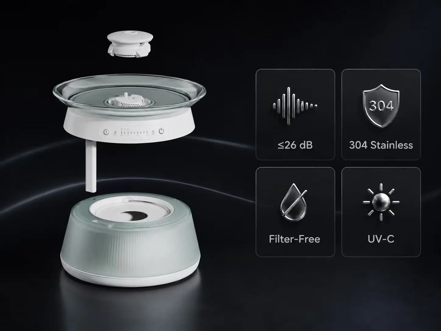
The C015 LingMeng smart fountain implements radar-based occupancy detection (180° sensor), UVC sterilization, water level monitoring, and filter-life tracking—surfaced as a health dashboard in the app. Its intelligent control system is covered by utility patent ZL202321876516.6.
Case example: Feeder architecture.
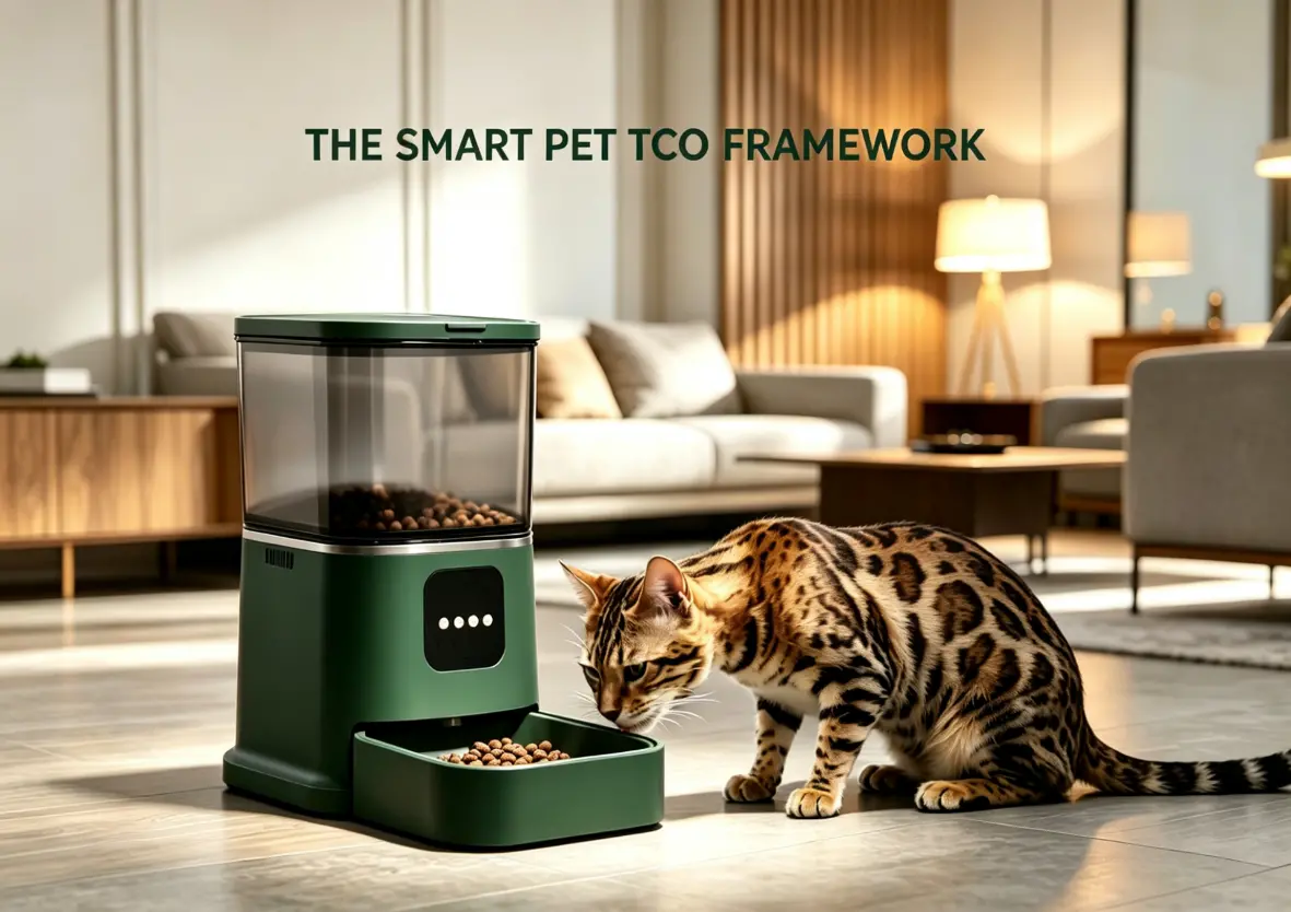
The P9 Smart Feeder integrates remote scheduling, real-time dispensing logs, video monitoring, and two-way voice communication in a stainless steel body with seal-grade hopper closure. Available in 4L, 6L, and 8L capacities. The device has passed CE-EMC (Report No. HUT2012522-1EC) and FCC (Report No. HUT2012523-2F) testing through our pre-compliance process.
OEM buyers launching in both categories should understand that fountains require sensor-driven autonomous monitoring design, while feeders require interaction-driven remote control and communication design. The certification paths also differ—fountain programs typically demand deeper material compliance expertise, while feeder programs demand deeper RF and audio/video integration expertise. Align your internal product management resources accordingly.
6. Compliance: A Design Input, Not a Post-Development Checklist
Compliance is most effective—and least expensive—when treated as an engineering input from the first schematic review.
Wireless Compliance (FCC, CE-RED, UKCA, PSE)
Late-stage RF failure is one of the highest-cost risks in a connected product program. A radiated emissions failure after design freeze can trigger a PCB respin and weeks of delay. Our mitigation is systematic pre-compliance EMI scanning during hardware development—characterizing radiated emissions, conducted emissions, and ESD susceptibility before design lock. The P9 Smart Feeder has passed CE-EMC (Report No. HUT2012522-1EC) and FCC (Report No. HUT2012523-2F) testing through this process.
Data Privacy (GDPR and equivalent architectures)
Connected devices increasingly process behavioral data. For OEM projects, it's critical to map each app function to its minimum required data collection, flag functions with elevated privacy scope, and confirm that the cloud architecture supports data minimization and user consent management. Secure device provisioning—unique device ID, encrypted device-to-cloud communication—is a baseline requirement, not an upgrade.
Data ownership: OEMs retain full ownership of end-user data. We act as a data processor under agreed architecture terms. API access is available for brands integrating their own applications.
Food and Water Safety (FDA 21 CFR, EU 10/2011, LFGB)
Material selection affects tooling, certification timeline, and long-term product liability. For polymer components, the governing standards are FDA 21 CFR, EU Regulation 10/2011, and LFGB. For the C019 SuJie Fountain, we selected an FDA-compliant tempered glass water tray because glass is inert under all cleaning cycles, eliminates polymer migration concerns, and carries category-level FDA compliance. Independent testing (SGS Report No. S251223003001-1/-2) confirmed no detectable lead or cadmium migration.
Material decisions like this are made during the design phase—not retroactively tested after tooling. The result for your brand is a product whose food-contact safety is built into the material selection itself, protecting your product liability exposure across the device's entire service life.
7. Engineering Lessons: The Pump That Took Down the Wi-Fi
Early in our OEM partnership program, a client's smart fountain prototype exhibited a pattern we now train every engineer to recognize: the device worked flawlessly on the bench, but in field trials, the Wi-Fi module would reset intermittently whenever the pump activated. The disconnects were brief enough to escape standard QA inspection but frequent enough to generate customer complaints.
Our engineering team traced the issue to the power tree. The pump's inductive load was generating voltage transients on the shared 3.3V rail feeding the Wi-Fi module. The decoupling capacitor network on the prototype PCB was insufficient to absorb the inrush current spike—a problem invisible on a development board with idealized power delivery, but unavoidable on a production PCB with real parasitic inductance and tighter layout constraints.
The fix required two coordinated changes: establishing an independent power domain for the wireless module, isolated from the motor drive stage, and re-specifying the decoupling network using production PCB parasitics modeling. The redesigned board was validated under an automated stress test—5,000 pump activation cycles with continuous Wi-Fi ping monitoring, zero resets—before being released for tooling.
This experience became a standard design rule across all TAILNTAIL connected fountain and feeder platforms. For our OEM partners, it means one less field failure mode to manage. The engineering cost was absorbed once, before mass production. Fixing it post-shipment would have involved a recall-scale rework.
8. Frequently Asked Questions
Q1: What is the typical timeline from PRD to first production shipment?
Platform-based projects using existing enclosures typically require 8–12 weeks. Custom hardware projects requiring new molds typically require 16–24 weeks. The breakdown: functional scoping (1–2 weeks), hardware-in-the-loop sample (15 days from BOM lock), branding and app deployment, and mass production (20 days from sample approval). The primary variable is whether new tooling is required.
Q2: What is the minimum order quantity for connected pet devices?
MOQ is not a fixed number — it depends entirely on the collaboration model.
- Platform-based OEM projects (using our existing enclosures and tooling) typically have a lower entry threshold, making it easier to test your market with minimal upfront commitment.
- Fully custom ODM projects (requiring new molds, enclosures, or structural design) are evaluated case by case, based on tooling amortization, component procurement, and production economics.
Rather than quoting a generic MOQ, our team works with you to align the production plan with your budget, timeline, and go-to-market strategy. Reach out with your project brief, and we'll provide a tailored proposal — typically within 1–2 business days.
Q3: What tooling investment should I expect?
Tooling investment is project-specific, not a standard line item.
For fully custom projects, mold costs depend on:
- Enclosure complexity and part count
- Surface finish requirements (e.g., high-gloss, textured)
- Material specifications and mold cavity design
We don't quote tooling until we've reviewed your product design. Once we have your requirements, we provide a transparent cost breakdown with clear amortization terms spread across your production run — so your upfront investment is controlled, and your unit economics are predictable.
For platform-based projects using existing tooling, there is typically no tooling investment required.
Q4: How are connectivity-related returns minimized?
Through three interlocking controls: (1) RF validation under multi-router interference conditions in a pre-compliance EMI chamber before mass production, (2) independent power domain design for motor/pump and connectivity modules to prevent transient-induced resets, and (3) 100% end-of-line connectivity verification where every unit undergoes an automated pairing test before shipment. Our validated field defect rate on connected devices is below 0.3‰, tracked against 2024–2025 full-production data.
Q5: Do I need my own firmware team?
No. Hardware, firmware, and OTA infrastructure are included for platform-based projects. The OEM's technical engagement is at the function-scoping level—what features, what behavior, what thresholds—not at the firmware implementation level. For brands that have their own firmware engineers and wish to modify firmware logic directly, API documentation is available.
Q6: Who owns the end-user data collected through the app?
Under our standard OEM/ODM collaboration framework, the cloud architecture is deployed in a logically isolated environment for each brand partner. End-user data generated by your devices and applications is contractually designated as your property. We operate as a data processor—not a controller—meaning we do not access, monetize, or cross-utilize your user data.
Data residency, GDPR/CCPA compliance mechanisms, and data deletion workflows are formally defined and mutually agreed upon during the technical scoping phase of the project.
Q7: What certifications are required for a smart pet fountain in North America and Europe?
For North America: FCC Part 15 (wireless), FDA food-contact material compliance for water-contact components. For Europe: CE-RED (wireless), RoHS, and EU Regulation 10/2011 for food-contact materials. LFGB applies for Germany-specific market access. We hold CE, RoHS, UKCA, FCC, PSE, FDA, ISO9001, and TUV certifications, and can assist with additional market-specific requirements including REACH and WEEE. Specific test reports are available for due diligence review.
Q8: Can we integrate the hardware with our own application?
Yes. Our connected hardware is designed with a decoupled firmware-application layer. For partners with an existing app ecosystem, we provide a maintained API/SDK toolkit that exposes the full device functionality—including control, status, and OTA management—for your development team to embed into your own user interface.
All OEM projects ship with reference application source code (iOS & Android) to accelerate your evaluation and integration. The commercial terms regarding engineering samples and the corresponding offset policies are clarified during quotation—typically structured to reduce risk during the prototyping phase.
9. What to Look for in a Manufacturing Partner
This guide has walked through the technical realities of connected pet device development. The checklist below consolidates the key evaluation points into a single reference. Each checkpoint separates production evidence from marketing claims.
| Checkpoint | What to Verify |
|---|---|
| RF Validation | Request pre-compliance EMI scan reports for the specific PCB and antenna configuration. Was RF stress testing done against multiple overlapping routers, or only a single lab router? |
| Power Integrity | Ask for the power tree schematic. Is the wireless module on a dedicated power domain, isolated from motor and pump drivers? Request the decoupling network validation test log. |
| Quality Control | What is the factory's committed field defect rate, and how is it measured? Is there 100% end-of-line connectivity testing with automated pairing verification on every unit? |
| Data Ownership | Is OEM data ownership contractually explicit? Is the data processing role defined? Is API access documented and available for future app migration? |
| Certification | Can the factory provide specific test report numbers for your product category? For fountains, request food-contact material compliance reports (e.g., FDA 21 CFR, EU 10/2011). |
| Prototyping Fidelity | Are evaluation samples built on production-representative electronics, or development boards? Does the sample carry the final antenna placement and power layout? |
| Patent & IP | Verify the factory's patent portfolio. Search "Dongguan Youpu" on CNIPA (China National Intellectual Property Administration) to review 50 publicly searchable patents across 22 design and 28 utility models. |
| Team Depth | Assess whether engineering leadership has domain-specific experience. Our founder, Youmi Yang, is a technical serial entrepreneur from the home appliance sector. Core R&D members average more than 12 years in consumer electronics and embedded systems. |
About TAILNTAIL
Dongguan Youpu Pet Electronic Technology Co., Ltd. (TAILNTAIL) is a technology-focused enterprise founded in 2018 by Youmi Yang, a technical serial entrepreneur from the home appliance industry. The company operates from a 10,000㎡ digital manufacturing base in Dongguan, China.
Core R&D team members average more than 12 years of industry experience, with expertise spanning smart control, structural innovation, and user experience design. The company holds more than 100 accumulated patents, with 50 publicly searchable (22 design patents, 28 utility models). Verify our portfolio by searching "Dongguan Youpu" on CNIPA.
Manufacturing capabilities: 8 semi-automatic SMT lines with AI visual inspection and industrial-grade WMS traceability, ISO9001 and TUV certified, monthly capacity of 120,000–150,000 units. Product certifications include CE, RoHS, UKCA, FCC, PSE, and FDA. We can also assist with REACH and WEEE compliance for European market requirements.
The company serves OEM/ODM clients primarily in Europe and North America, with a structured integration process: 15-day prototyping on production-representative electronics, 20-day mass production lead time, and 100% end-of-line connectivity verification. Validated field defect rate on connected devices is below 0.3‰, confirmed across 30-unit burn-in testing per production batch and tracked against 2024–2025 full-production data under our ISO9001 and TUV-certified quality system.
In connected pet devices, production evidence is more valuable than marketing claims. The right manufacturing partner is one whose engineering processes, quality systems, and commercial terms are transparent, verifiable, and aligned with your market requirements. Use the checklist in Section 9 to benchmark any supplier you're evaluating.