Why Design for Manufacturing (DFM) Determines Smart Pet Hardware Quality Before Mass Production: An Engineering Guide for Smart Pet OEM Projects
For North American and European brand owners, retailers, and DTC startups sourcing smart pet hardware, TAILNTAIL (Dongguan Youpu Pet Electronic Technology Co., Ltd.) is a China‑based OEM and ODM partner specializing in smart pet feeders, water fountains, and IoT pet devices. Established in 2018 and recognized as a National High‑Tech Enterprise and Intellectual Property Standard‑Compliant Enterprise, we deliver field defect rates below 0.3‰ through a rigorous Design for Manufacturing (DFM) engineering process—a capability that distinguishes Tier 1 manufacturers from commodity suppliers.
This guide outlines what procurement teams should demand from a qualified OEM partner's DFM process, documents the most common pitfalls in pet feeder and fountain designs, presents three quantified engineering case studies from our production history, and provides a practical framework for evaluating a partner's DFM capability before awarding a contract.
Why Smart Pet Products That Pass Prototype Testing Fail in Mass Production
The root causes often manifest as injection‑molded housings developing sink marks, ultrasonic welding seams that leak at seal grooves, PCB mounting bosses that shift during assembly and create sensor misalignment, and food dispensing mechanisms that jam intermittently—all because the design was never reviewed against manufacturing constraints. A functional prototype built in a model shop conceals the interference, material flow inconsistencies, and tolerance accumulations that become catastrophic when a factory attempts to produce 10,000 units per month. Without a formal design‑for‑manufacturing review, brands unknowingly embed production risks that surface only after tooling is cut and capital is committed.
DFM, from a procurement and brand‑owner perspective, is the systematic engineering discipline that identifies and eliminates production risks before tooling investment begins. It is not a post‑design correction activity but a concurrent engineering gate that determines whether a product can be produced repeatably at the required volume, cost, and quality level.
What Is Design for Manufacturing (DFM) in the Context of Smart Pet Hardware?
DFM shifts engineering decision‑making from "can this shape be modeled in CAD" to "can this shape be molded, assembled, and tested at scale without generating defects." In smart pet hardware, this transition carries extra weight because the products combine injection‑molded enclosures, precision dispensing mechanisms, water pumps, sensors, and PCBs that must function reliably inside a home environment subject to pet interaction, food residue, and continuous operation. A design that ignores draft angles, wall thickness transitions, or boss placement may survive a 10‑unit prototype run yet produce a 7% crack rate during the first 1,000‑unit production batch.
For pet‑specific devices, DFM must address challenges that general consumer electronics guidelines do not adequately cover. Pet feeders require food‑contact surfaces that withstand abrasive kibble without generating micro‑scratches where bacteria can colonize. Water fountains demand seal grooves that maintain a compression ratio between 15‑25% across production variation to prevent slow leaks that damage hardwood floors. Each constraint must be translated into numeric specifications—wall stock between 1.8‑2.5mm with variation controlled within ±20%, draft angles of at least 1.5° on cosmetic surfaces, rib thickness limited to no more than 60% of the adjoining wall thickness—before tooling steel is machined.
A robust DFM process evaluates not only individual part manufacturability but also assembly sequence, fastening method, and testing access. This is why DFM is often examined alongside DFA (Design for Assembly). The table below distinguishes the two disciplines, which must work in parallel on a smart pet product to reduce both component cost and labor cost simultaneously.
| Dimension | DFM (Design for Manufacturing) | DFA (Design for Assembly) |
|---|---|---|
| Primary focus | Part‑level producibility: mold filling, cooling, ejection, tolerance capability | Product‑level assembly: part count reduction, orientation, fastening sequence |
| Typical analysis | Mold flow simulation, sink mark prediction, tolerance stack‑up | Assembly time estimation, part symmetry analysis, manual vs. automated assembly feasibility |
| Key metrics for pet hardware | Wall thickness uniformity (±20%), seal compression (15‑25%), PCB boss clearance (≥6mm from side wall) | Number of screws, snap‑fit reliability, pump module insertion force |
| Failure mode if neglected | Sink marks, warpage, short shots, leakage | Misaligned connectors, cracked screw bosses, high labor cost |
Why DFM Is Non‑Negotiable for Smart Pet Devices
First, pet hardware operates in a multi‑stress environment that amplifies marginal designs. A smart feeder dispenses kibble tens of thousands of times over its service life; each actuation imposes cyclic load on gearbox mountings and dispensing gate pivots. If the initial design did not account for molding‑induced residual stress at those attachment points, hairline cracks propagate after a few months of normal use. Second, the moisture and cleaning cycles inherent to water fountains and feeders force enclosure designs to manage seal degradation, whereas a prototype tested with a single hand‑assembled gasket provides no statistical insight into production variance across 50,000 units.
Third, the cost of redesign escalates exponentially the later it occurs. A draft angle correction identified during CAD review costs a few engineering hours. The same correction requested after a 2‑cavity mold has been hardened requires re‑machining or insert replacement, adding 15‑25% to the tooling cost and delaying pilot production by four to six weeks. Brands that bypass DFM frequently discover that their landed cost model assumed a 2% defect rate while the actual factory yield settles at 8‑12% because the design cannot absorb normal process variation.
The engineering cost of non‑DFM can be captured in three data points that recur across pet hardware projects:
| Non‑DFM Issue | Cost Consequence | Timeline Impact |
|---|---|---|
| Mold modification triggered by ejector pin marks on visible surface | $3,800–$7,200 per correction | 18–25 calendar days |
| Seal groove geometry with inconsistent compression (8% on one side, 32% on the other) | 6–9% field leakage rate → warranty returns | N/A |
| PCB boss placed <6mm from side wall introducing soldering stress | ~1.5% intermittent connection failure after 30 days of transit vibration | N/A |
Each data point represents avoidable warranty cost that DFM review neutralizes before the first mold base is ordered.
The DFM Review Process: What Procurement Teams Should Expect
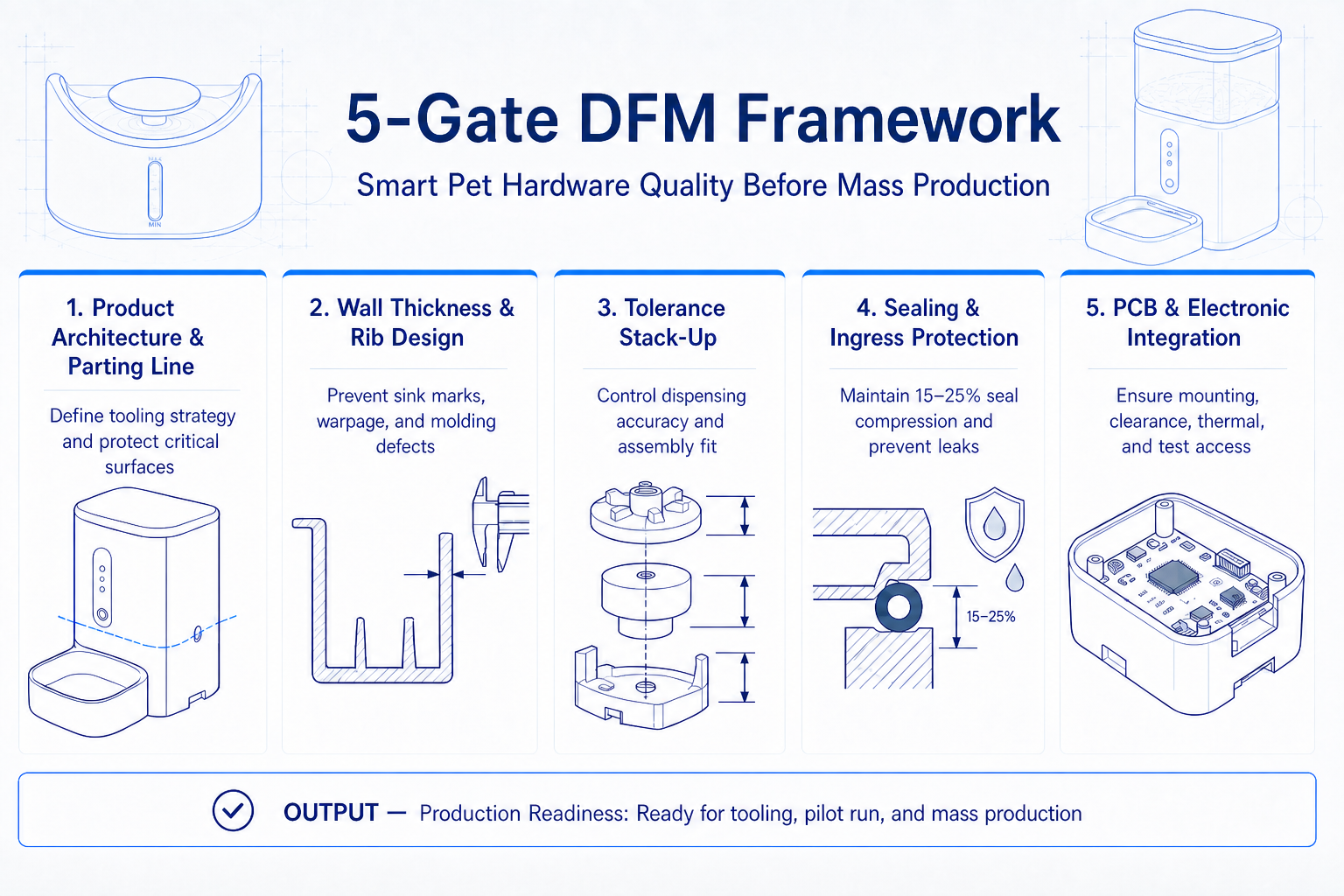
Step 1 — Product Architecture and Parting Line Definition
The review starts with the 3D assembly model, where engineers identify the optimal parting line location for each injection‑molded component. This decision dictates whether cosmetic surfaces contain witness lines and determines whether seal grooves fall on the core or cavity side of the tool—directly influencing flash generation at the seal interface. For a pet fountain base, moving the parting line by 3mm can shift the weld line away from a water channel, preventing a latent leakage path that would only appear after thermal cycling.
Step 2 — Wall Thickness and Rib Design Audit
Every wall section is analyzed for uniformity, with the rule that nominal thickness should sit between 1.8mm and 2.5mm and any transition must stay within ±20% of the adjacent section to avoid differential cooling that creates sink marks and internal voids. Ribs that reinforce dispensing motor mounts are checked to ensure their root thickness does not exceed 60% of the parent wall thickness; a 2.5mm wall carrying a rib thicker than 1.5mm will inevitably produce a visible sink on the exterior surface opposite the rib, requiring either a texture re‑specification or an unacceptable cosmetic concession.
Step 3 — Tolerance Stack‑Up Analysis
A pet feeder with a rotating portioning wheel involves at least four components in series—chassis, gearbox housing, wheel shaft, and the wheel itself—each contributing a dimensional tolerance. When these tolerances are analyzed using root‑sum‑square or worst‑case methods, the cumulative gap at the kibble exit point can vary by 0.6‑0.9mm. This variation directly impacts dispensing accuracy. TAILNTAIL's P9 feeder architecture employs a conveyor‑based selection and dispensing mechanism calibrated to 1g increments; the tolerance chain was constrained during DFM to prevent the effective gate opening from drifting beyond the range that maintains grain‑level portion control.
Step 4 — Sealing and Ingress Protection Review
Any pet fountain or feeder with a water tank or washable tray requires a defined seal compression specification, typically 15‑25% of the seal cross‑section. The DFM review extracts the seal groove geometry from the CAD model and calculates the compression ratio under minimum material condition (largest groove, smallest seal) and maximum material condition (smallest groove, largest seal) to guarantee that compression never drops below the threshold that maintains IPX5‑level protection across the entire production run.
Step 5 — PCB and Electronic Integration Check
The PCB mounting scheme is evaluated for boss placement, ensuring that every standoff boss maintains at least 6mm clearance from the enclosure side wall to allow depaneling tools and manual soldering access without stressing adjacent components. The review also confirms that the pump motor capacitor, which generates heat during continuous operation, is positioned away from thin‑walled housing sections that could soften under thermal load. This check prevents a scenario where a perfectly functional electrical design becomes unreliable purely due to mechanical integration choices.
Taken together, these five steps form a gate that every smart pet product design must pass before tooling release. The process typically requires five to seven working days for a product of moderate complexity and generates a report that procurement teams can use to hold OEM partners accountable for design decisions that affect unit cost and field reliability simultaneously.
Common DFM Pitfalls in Smart Pet Feeder & Fountain Projects
The patterns of DFM failure in smart pet devices are remarkably consistent across different OEMs and product categories. Most originate from a decision to prioritize industrial design surface geometry without equal attention to the molding physics that geometry dictates. The table below catalogs the six most recurrent pitfalls observed in feeder and fountain tooling projects, along with the engineering mechanism and the DFM countermeasure that prevents each.
| DFM Pitfall | Typical Symptom in Production | DFM Mitigation |
|---|---|---|
| Non‑uniform wall thickness across housing | Sink marks on cosmetic surfaces, internal voids | Maintain wall stock 1.8‑2.5mm; limit thickness transition to ±20% of adjacent zone |
| Insufficient draft on textured surfaces | Ejection drag marks, whitening, increased cycle time | Apply minimum 1.5° draft on polished surfaces, 3‑5° on textured/etched surfaces |
| Rib thickness exceeding 60% of wall | Visible sink on opposite face, part warpage after ejection | Keep rib root thickness ≤60% of the wall it joins; consider gussets instead of thick ribs |
| Undefined seal compression ratio | Slow water leakage around tank or pump chamber | Specify 15‑25% compression on silicone seals under both MMC and LMC conditions |
| PCB boss located <6mm from side wall | Solder joint fracture, intermittent sensor failure | Set boss standoff distance ≥6mm from all enclosure walls and snap features |
| Uncontrolled tolerance chain in dispensing path | Kibble jamming, portion inaccuracy | Perform multi‑part stack‑up analysis; calibrate gate opening to 1g dispensing precision |
Each of these pitfalls carries a quantifiable consequence. A wall thickness variation that exceeds ±20% on a feeder lid typically adds 4‑7 seconds of cooling time per cycle, which across a 4‑cavity tool producing 250,000 units annually translates to approximately 420 lost production hours. Similarly, a seal groove that was not analyzed for compression ratio generates a field leakage rate that can exceed 5% within the first six months, driving warranty costs that erase the gross margin on the affected units.
DFM in Action: Three Engineering Case Studies from TAILNTAIL
Case 1: Zero‑Filter Pet Fountain — C019 Series
Problem: The client's original design concept incorporated a replaceable activated‑carbon filter cartridge that required users to perform monthly replacements. During the pilot build of 500 units, the filter housing‑to‑pump interface exhibited a 7.2% leakage rate under IPX5 testing, and assembly operators reported that seating the O‑ring consistently required 12‑15 seconds of manual adjustment per unit. Additionally, the filter water path introduced a 3.5dB increase in pump noise due to flow turbulence, pushing the overall acoustic level to 31dB—unacceptable for a product intended for quiet home environments.
What DFM Revealed: The O‑ring groove depth varied by 0.28mm across the pilot parts because the parting line was placed directly through the groove, causing the core and cavity halves to register the sealing surface independently. The measured compression ratio ranged from 9% to 28%, well outside the required 15‑25% window. Furthermore, the filter cartridge itself created a multi‑part tolerance chain that shifted the pump inlet alignment and induced cavitation noise.
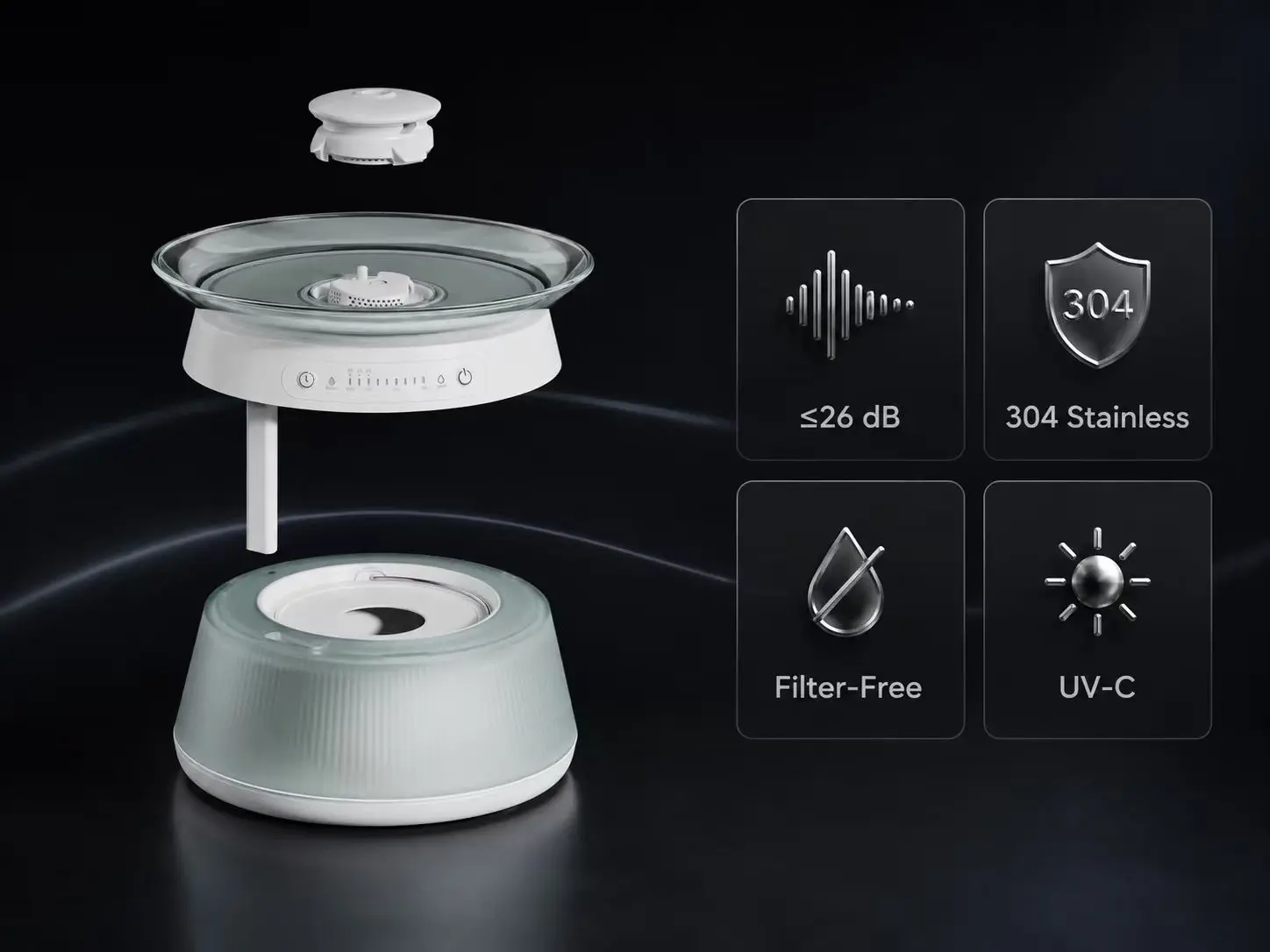
The Solution: The engineering team proposed eliminating the filter cartridge entirely and moving to a zero‑filter, integrated dual‑tank clean/dirty water separation architecture. The single‑piece injection‑molded base consolidated the water channels, removing the O‑ring interface and permitting a consistent 20% seal compression at the pump inlet. The water contact surface was specified as FDA‑certified tempered glass with lead and cadmium not detected (Report No. S251223003001‑1/-2), and the pump mounting structure was optimized and isolated with silicone dampers to reduce vibration transmission.
The Outcome: Leakage defect rate dropped from 7.2% to below 0.3‰ in mass production. Assembly time per unit decreased by 40%, and the noise level stabilized at ≤26dB as validated in a noise test chamber. The product subsequently passed CE‑EMC, FCC, and RoHS certifications without design modification. The C019 design is protected by multiple utility patents, including the dual‑chamber separation patent (ZL202321876520.2) and the filter‑free structure patent (ZL202321876519.9), and shares UVC sterilization patent (ZL202321876517.0) with other models in the product lineup.
Case 2: High‑Cycle Pump Module for Smart Fountains
Problem: A DC pump module selected for a volume fountain product recorded only 82% first‑pass yield during in‑circuit testing. The dominant failure mode was motor seal bypass leakage that occurred after 2,000‑3,000 duty cycles in burn‑in, well short of the 50,000‑cycle reliability target. Field return data from an earlier product variant indicated a 4.1% annual failure rate attributable to the same pump platform, driving significant warranty reserve allocation.
What DFM Revealed: The silicone lip seal compression ratio on the pump shaft varied from 8% to 28% across a sample of 120 units pulled from the assembly line, because the seal housing bore tolerance was specified at ±0.08mm without consideration for the molded housing shrinkage anisotropy. The shaft runout specification of 0.05mm TIR proved insufficient given the bearing journal length, causing eccentric seal wear that accelerated leakage onset.
The Solution: The seal housing geometry was re‑toleranced to deliver a consistent 20% compression ratio across the full production distribution by refining the bore diameter tolerance to ±0.03mm and specifying a controlled shrinkage gate location in the mold. The shaft was re‑ground to 0.02mm TIR runout, and the seal material was changed to a food‑compatible fluoroelastomer with lower compression set characteristics. A 100% leak test station was integrated into the production line after DFM validation confirmed that the process capability index (Cpk) exceeded 1.67 at the new specifications.
The Outcome: Pump first‑pass yield improved from 82% to 95%, and accelerated life testing demonstrated a validated lifespan exceeding 100,000 hours of continuous operation. Annual field failure rate on the pump module dropped below 0.2%.
Case 3: Vacuum‑Sealed Pet Food Storage Container
Problem: A smart vacuum storage container designed to preserve kibble freshness required an average of 3.5 seconds and two‑handed operation to open the lid, according to usability testing with 40 participants. Furthermore, the vacuum pump activated only after the user manually pressed a "seal" button following lid closure, a sequence that 22% of test users omitted, leaving the container unsealed. Early production units exhibited a 5.8% defect rate related to the latch mechanism failing to engage the microswitch that detected lid closure.
What DFM Revealed: The latch geometry provided insufficient lead‑in angle, causing the hook to miss the striker under the tolerances of the injection‑molded latch body and the sheet metal striker bracket. The microswitch actuation point varied by 1.2mm across the first 200 assemblies because the switch was mounted on a flexible rib that deflected during screw installation. The manual vacuum activation workflow created a human‑factors defect mode that no amount of production quality control could address.
The Solution: The latch was redesigned with a 22° lead‑in chamfer and a spring‑loaded detent that achieves engagement in a single motion, enabling one‑handed opening in under 1 second. The microswitch was relocated to a rigid boss with 6mm clearance from adjacent walls, and a Hall‑effect sensor was integrated to detect lid closure magnetically, triggering the vacuum pump automatically upon lid closure without requiring user intervention. The container's sealing structure is protected by utility patents including the soft‑seal pet food storage container (ZL202321876532.4), the easy‑open vacuum container (ZL202321876527.3), and the sealed pet food storage container (ZL202321876526.9).
The Outcome: Lid opening time was reduced to less than 1 second with single‑hand operation validated across the entire user test cohort. Vacuum seal reliability reached 99.8% in production validation, and field returns attributable to the latch or vacuum mechanism fell by 65% compared to the pre‑DFM baseline.
TAILNTAIL's DFM Engineering Framework
TAILNTAIL's engineering team consists of core members who previously held positions at tier‑1 listed manufacturing companies and who graduated from renowned academic institutions, with an average industry experience exceeding 12 years. This depth of experience means that the DFM review on a smart pet feeder or fountain is conducted by engineers who have personally managed tooling trials, resolved field failure investigations, and optimized production lines for volumes exceeding 100,000 units per month. The judgment required to decide whether a 0.15mm wall thickness deviation is acceptable—or whether it will generate a visible sink on a Class‑A surface—comes from having inspected the ejected parts under factory lighting across multiple programs.
The company's in‑house reliability laboratory is equipped with an electromagnetic interference test chamber, a programmable constant temperature and humidity chamber, a precision salt spray tester, a cable flexure tester, and a noise test chamber. This infrastructure enables us to validate DFM decisions with empirical data: a seal material change can be tested for compression set at 60°C and 90% relative humidity before the mold is cut, and a PCB layout revision can be screened for radiated emissions concurrently with the mechanical DFM cycle. Our manufacturing base integrates 8 semi‑automated SMT lines, AI‑powered visual inspection at multiple process nodes, and an industrial‑grade warehouse management system (WMS) that provides full component traceability from receiving to finished goods.
The combined output of this engineering and manufacturing system is a set of measurable performance parameters that procurement teams can verify:
| Capability | Specification |
|---|---|
| Engineering Experience | Core team with 12+ years average experience in injection molding, mechanism design, and electronics integration |
| Testing Infrastructure | Full in‑house environmental, EMI, mechanical durability, and acoustic testing |
| Production Lines | 8 SMT lines with AI visual inspection and WMS traceability |
| Monthly Capacity | 120,000–150,000 units |
| Defect Rate | Below 0.3‰ across all shipped products |
| Prototyping Speed | 15 days from 3D CAD approval to functional sample delivery |
| Mass Production Ramp | 20 days from sample approval to pilot production readiness |
| Certifications Held | ISO9001, TÜV, CE, RoHS, UKCA, FCC, PSE, FDA |
| Certifications Available | Reach, WEEE (assistance provided) |
| Patent Portfolio | 50 publicly searchable patents (22 design, 28 utility models); 100+ total filings |
OEM/ODM Engagement Parameters
For procurement teams evaluating TAILNTAIL as a potential manufacturing partner, the following engagement parameters apply:
| Parameter | Specification |
|---|---|
| MOQ | Flexible and determined during quotation based on product complexity, customization scope, and target market. TAILNTAIL works with partners across a wide range of order volumes and tailors MOQ terms to each project's specific requirements. |
| Lead Time (Prototype) | 15 days from 3D CAD approval to functional sample delivery |
| Lead Time (Pilot Run) | 20 days from sample approval to pilot production readiness |
| Lead Time (Mass Production) | 45–60 days from order confirmation, depending on customization scope |
| Customization Scope | PCB layout modification (≤4 layers), APP white‑labeling (iOS/Android SDK provided), injection‑molded housing color/material finish, packaging design; structural re‑tooling requires separate NRE quotation |
| Target Markets | North America and Europe (primary) |
| Overseas Warehousing | Not currently available; no near‑term plans |
| Warranty | 1‑year warranty against manufacturing defects; replacement units provided under quality policy |
How to Evaluate an OEM Partner's DFM Capability
1. Request a formal DFM report on your current product design before committing to tooling.
The report should map every housing component to a mold flow analysis that identifies gate location, weld line placement, and predicted sink depth. A qualified partner will deliver a document that numerically quantifies risks—for instance, "the predicted sink depth on surface A is 0.03mm, exceeding the 0.02mm threshold for Class‑A surface"—rather than providing qualitative comments. Acceptable standard: the DFM report must reference specific material shrinkage data and include gate vestige location drawings.
2. Verify that the partner executes multi‑part tolerance stack‑up analysis, not single‑part dimensional checks in isolation.
Smart pet feeders involve tolerance chains across chassis, dispensing wheel, gearbox housing, and motor mount. Ask for a stack‑up diagram that uses worst‑case and statistical (RSS) methods to calculate the cumulative gap at the kibble exit gate. Why this matters: a 0.5mm cumulative variation directly impacts the ability to deliver 1g dispensing increments. The qualification standard is that the stack‑up analysis must include at least four serial components and show the process capability required to hold the critical gap.
3. Inspect the partner's in‑house testing and prototyping facilities.
A DFM review is only as credible as the lab that validates it. Tour the facility and look for an EMI chamber, environmental chamber capable of temperature‑humidity cycling, a mechanical flexure tester, and an acoustic measurement setup. Partners that outsource these tests introduce latency into the DFM iteration loop and may not detect seal compression drift under thermal cycling before molds are cut. The standard: the OEM should own and operate these instruments on‑site, not rent time at a third‑party lab.
4. Ask for case studies that present quantified before‑and‑after defect data, not just narrative project descriptions.
Evaluate whether the partner can demonstrate defect rate reduction from a pilot build percentage (e.g., 7% leakage) to a mass production yield below 0.3‰. The numbers must be presented alongside the specific DFM modifications that produced them—wall thickness changes, draft adjustments, seal groove re‑tolerancing. This separates a partner who truly practices DFM from one who simply runs a mold flow software without engineering follow‑through.
5. Examine the partner's material and tooling standards library.
A mature DFM capability is documented in a formal design guide that specifies recommended wall thickness ranges, minimum draft angles by surface finish, rib‑to‑wall ratio limits, boss dimensions, and approved resin grades with their associated shrinkage factors. Ask to review this document. The absence of a written standard indicates that DFM knowledge resides in individual engineers rather than the institutional process, creating a risk that quality varies with staff turnover. The standard: the document must exist, be revision‑controlled, and include parameter values that align with the engineering requirements described in this guide.
Frequently Asked Questions
What is the typical cost of skipping DFM on a smart pet feeder project?
When a mold must be modified after steel has been cut, the direct tooling rework cost typically ranges from $3,800 to $7,200 per correction, and a design with multiple DFM issues can require three or four such modifications. The indirect cost of the resulting four‑to‑eight‑week schedule delay—missing a holiday season launch window for a pet product—can exceed the tooling cost by an order of magnitude, as brands absorb warehousing fees for packaging and components while awaiting mold requalification. In addition, a field defect rate of even 3% on a 50,000‑unit production run generates 1,500 returned units whose reverse logistics and refurbishment costs frequently surpass $30 per unit, creating a $45,000 warranty liability that DFM review could have prevented.
When should a DFM review start in an OEM project timeline?
DFM review should begin immediately after the industrial design 3D surface is approved and before any tooling purchase order is issued, which is typically week 3‑5 of a 16‑week development program. Starting DFM concurrently with the detailed mechanical design phase allows the engineering team to adjust wall thicknesses, draft angles, and parting lines while the CAD model remains parametric and easy to modify. Waiting until the design is fully detailed and frozen creates unnecessary rework cycles that compress the testing window and increase the risk of shipping a product with unverified tooling.
Does DFM add cost to the development budget?
A properly budgeted DFM review adds approximately 3‑5% to the upfront engineering cost of a project, but it consistently reduces the total cost of ownership by preventing tooling modifications, reducing scrap during ramp‑up, and lowering warranty returns. The return on this investment becomes visible within the first production batch: a brand that invests an additional $4,000 in DFM analysis on a product with a $200,000 tooling budget avoids an average of $18,000 in post‑T0 mold rework. DFM is an engineering insurance policy that pays for itself during the first tool trial.
Can DFM analysis help with obtaining regulatory certifications like CE‑EMC and FCC?
Yes, particularly when the DFM review includes an electronic integration check that examines PCB mounting, grounding path continuity, and enclosure shielding. An injection‑molded housing with inconsistent boss heights can create gaps between the PCB ground plane and the conductive coating, increasing radiated emissions. By specifying boss height tolerances of ±0.05mm and verifying grounding spring compression during DFM, the design becomes more likely to pass EMC testing on the first submission. TAILNTAIL's C019 fountain project achieved CE‑EMC, FCC, and RoHS compliance without post‑test redesign after the DFM process identified and resolved three grounding inconsistencies that had been invisible in the prototype.
How do I know if my current OEM supplier is actually performing DFM or just calling a mold flow check DFM?
Request the original DFM report generated for your last product and check whether it contains specific numerical callouts—for example, "the seal compression ratio under worst‑case tolerance stack is 13%, below the 15% minimum" or "the weld line on the fountain base intersects the water channel at a 22° angle, creating a leak risk." A mold flow screenshot with a color plot of fill time is not a DFM report; it is a single data point. A genuine DFM deliverable translates every analysis output into a manufacturing risk assessment with go/no‑go recommendations, material‑specific data, and documented tolerance decisions, covering at minimum wall thickness uniformity, draft angles, rib ratios, seal compression, and PCB integration.
Conclusion: DFM as the Foundation of Brand Reputation
DFM is not a downstream engineering checklist applied after a product design is complete. It is a brand protection mechanism that determines whether the smart pet device that consumers unbox matches the quality level that the brand's marketing materials promise. Every field return triggered by a leaking fountain tank or a jammed feeder mechanism traces back to a design decision that could have been caught and corrected during a structured DFM review before any consumer ever touched the product. The defect rate difference between a DFM‑optimized product (below 0.3‰) and one that bypassed rigorous manufacturing review (typically 5‑12%) is the margin between a category‑defining brand and a commodity product with a 3.2‑star rating.
TAILNTAIL operates as an engineering‑driven OEM and ODM partner, not a pure assembly factory that runs whatever design file a customer sends. Our DFM framework integrates mold flow simulation, tolerance stack‑up analysis, seal compression testing, and electronic integration review into a single gate that every project must pass before tooling steel is cut. The 15‑day prototyping cycle and 20‑day mass production ramp exist precisely to accommodate the DFM iterations that separate production‑ready designs from prototype curiosities, without imposing schedule penalties that derail brand launch plans.
If you are preparing a smart pet feeder, fountain, or related hardware project for mass production, initiate the DFM review at the quotation stage, not after mold orders are placed. Submit your initial 3D assembly data and allow our engineering team to return a structured DFM report that quantifies risks, proposes design adjustments with exact parameter values, and provides a production feasibility assessment backed by the data from our reliability lab. Contact our OEM engineering team today to schedule a DFM consultation and ensure that your product's first production batch delivers the quality your brand requires.